 |
Electronic Components Datasheet Search |
|
|
Electronic Components Datasheet Search |
|
The question interval is too short.
Please try again in a few seconds.

Hello, Please ask a question about E39-R1 Datasheet
# Example questions:
➢ What are the voltage ranges supported by both the relay and dc transistor output models of the e3jk sensors?
➢ What is the ip rating for the protective structure of these sensors?
➢ What is the standard cable length for the pre-wired models of the e3jk photoelectric sensors?
| Part No. | E39-R1 |
| Manufacturer | ETC |
| Size | 329 Kbytes |
| Pages | 8 pages |
| Description | Built-in power supply photoelectric sensor |


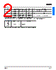



1. General Overview & Models
️· Product: E3JK Photoelectric Sensor
️· Types: The data covers Through-beam, Retroreflective, and Diffuse-reflective models.
️· Model Naming: E3JK followed by a suffix that indicates variations in output, timing, and features (e.g., E3JK-5M1, E3JK-R2S3).
️· Purpose: Used for object detection and sensing.
️· Accessories: Mounting brackets, reflector (for retroreflective models), instruction manual
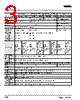
2. Technical Specifications (Shared Across Models)
️· Protective Structure: IEC60529 IP64 (dust and water resistant)
️· Connection Method: Pre-wired models (standard length: 2 m)
️· Weight (Packed): Approximately 420g (Through-beam & Retroreflective), Approximately 250g (Diffuse-reflective)
️· Materials:
- Case: ABS
- Lens: Acrylics
- Mounting Bracket: Steel
️· Operating Voltage: Can vary, 24-240 VAC or 12-240 VDC are mentioned.
️· Note: The output stage leakage currents are 0.1 mA max.
3. Model-Specific Outputs & Circuits
This is the most complex section, detailing different output types:
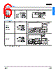
️· Relay Output (e.g., E3JK-5M1, E3JK-R2M2, E3JK-R4M2, E3JK-DS30M2):
- "Light indicator (red)" - likely a status LED.
- L-ON (Ta) - Light ON mode
- D-ON (Ta) - Dark ON mode
- Includes a built-in relay (G6C).
- Wiring: Power source, Main circuit (Polarity Optional), 24 to 240 VAC, 12 to 240 VDC, White, Brown, Blue, Black, Contact output.
️· DC Transistor Output (e.g., E3JK-5S3, E3JK-R2S3, E3JK-R4S3, E3JK-DS30S3):
- Similar L-ON and D-ON modes.
- Wiring: Power source, Main circuit, Load, Gray (D-ON), Black (L-ON), Drive circuit.
️· Specialized DC Transistor Output (E3JK-R2R3):
- Designed for specific load requirements.
- Notes: Connect to brown and blue on the emitter side. Output Stage limitation: I1 + I2 < 100 mA
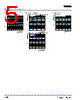
4. Performance Characteristics (Illustrative Diagrams)
️· Excess Gain Ratio vs. Setting Distance:
- Shows how the sensor's gain changes with distance for Through-beam, Retroreflective, and Diffuse-reflective models.
- Used to set appropriate distance for best sensor performance.
- Includes diagrams with various distance ranges (0-5m) and corresponding gain values.
5. Diagrams and Wiring
️· Output Circuit Diagrams: Detailed illustrations showing the electrical connections for the different output types (Relay and DC Transistor). These diagrams specify wire colors and connection points.
Key Takeaways & Cautions:
️· Careful Model Selection: The E3JK family offers multiple models with different output types and performance characteristics. Selecting the correct model for your application is critical.
️· Wiring Diagrams: Refer to the output circuit diagrams *very* carefully when wiring the sensor. Incorrect wiring can damage the sensor or the connected load.
️· Load Limits: The DC Transistor Output (especially the E3JK-R2R3 variant) has load limits. Exceeding these limits can damage the sensor.
️· Setting Distance: Adjust the sensor's setting distance to optimize performance. The diagrams show the relationship between distance and gain.
️· Polarity: Some models indicate "Polarity Optional" for the main circuit.
1. General Overview & Models
️· Product: E3JK Photoelectric Sensor
️· Types: The data covers Through-beam, Retroreflective, and Diffuse-reflective models.
️· Model Naming: E3JK followed by a suffix that indicates variations in output, timing, and features (e.g., E3JK-5M1, E3JK-R2S3).
️· Purpose: Used for object detection and sensing.
️· Accessories: Mounting brackets, reflector (for retroreflective models), instruction manual
2. Technical Specifications (Shared Across Models)
️· Protective Structure: IEC60529 IP64 (dust and water resistant)
️· Connection Method: Pre-wired models (standard length: 2 m)
️· Weight (Packed): Approximately 420g (Through-beam & Retroreflective), Approximately 250g (Diffuse-reflective)
️· Materials:
- Case: ABS
- Lens: Acrylics
- Mounting Bracket: Steel
️· Operating Voltage: Can vary, 24-240 VAC or 12-240 VDC are mentioned.
️· Note: The output stage leakage currents are 0.1 mA max.
3. Model-Specific Outputs & Circuits
This is the most complex section, detailing different output types:
️· Relay Output (e.g., E3JK-5M1, E3JK-R2M2, E3JK-R4M2, E3JK-DS30M2):
- "Light indicator (red)" - likely a status LED.
- L-ON (Ta) - Light ON mode
- D-ON (Ta) - Dark ON mode
- Includes a built-in relay (G6C).
- Wiring: Power source, Main circuit (Polarity Optional), 24 to 240 VAC, 12 to 240 VDC, White, Brown, Blue, Black, Contact output.
️· DC Transistor Output (e.g., E3JK-5S3, E3JK-R2S3, E3JK-R4S3, E3JK-DS30S3):
- Similar L-ON and D-ON modes.
- Wiring: Power source, Main circuit, Load, Gray (D-ON), Black (L-ON), Drive circuit.
️· Specialized DC Transistor Output (E3JK-R2R3):
- Designed for specific load requirements.
- Notes: Connect to brown and blue on the emitter side. Output Stage limitation: I1 + I2 < 100 mA
4. Performance Characteristics (Illustrative Diagrams)
️· Excess Gain Ratio vs. Setting Distance:
- Shows how the sensor's gain changes with distance for Through-beam, Retroreflective, and Diffuse-reflective models.
- Used to set appropriate distance for best sensor performance.
- Includes diagrams with various distance ranges (0-5m) and corresponding gain values.
5. Diagrams and Wiring
️· Output Circuit Diagrams: Detailed illustrations showing the electrical connections for the different output types (Relay and DC Transistor). These diagrams specify wire colors and connection points.
Key Takeaways & Cautions:
️· Careful Model Selection: The E3JK family offers multiple models with different output types and performance characteristics. Selecting the correct model for your application is critical.
️· Wiring Diagrams: Refer to the output circuit diagrams *very* carefully when wiring the sensor. Incorrect wiring can damage the sensor or the connected load.
️· Load Limits: The DC Transistor Output (especially the E3JK-R2R3 variant) has load limits. Exceeding these limits can damage the sensor.
️· Setting Distance: Adjust the sensor's setting distance to optimize performance. The diagrams show the relationship between distance and gain.
️· Polarity: Some models indicate "Polarity Optional" for the main circuit.
| Part No. | E39-R1 |
| Manufacturer | ETC |
| Size | 329 Kbytes |
| Pages | 8 pages |
| Description | Built-in power supply photoelectric sensor |
| Does ALLDATASHEET help your business so far? [ DONATE ] |
About Alldatasheet | Advertisement | Contact us | Privacy Policy | Link to Datasheet | Link Exchange | Manufacturer List All Rights Reserved©Alldatasheet.com |
| Russian : Alldatasheetru.com | Korean : Alldatasheet.co.kr | Spanish : Alldatasheet.es | French : Alldatasheet.fr | Italian : Alldatasheetit.com Portuguese : Alldatasheetpt.com | Polish : Alldatasheet.pl | Vietnamese : Alldatasheet.vn Indian : Alldatasheet.in | Mexican : Alldatasheet.com.mx | British : Alldatasheet.co.uk | New Zealand : Alldatasheet.co.nz |
|
Family Site : ic2ic.com |
icmetro.com |
 British ▼
  English
 Chinese
 German
 Japanese
 Russian
 Korean
 Spanish
 French
 Italian
 Portuguese
 Polish
 Vietnamese
 Indian
 Mexican
 New Zealand