 |
Electronic Components Datasheet Search |
|
|
Electronic Components Datasheet Search |
|
The question interval is too short.
Please try again in a few seconds.

Hello, Please ask a question about M2AMS2-3A-R2/N Datasheet
# Example questions:
➢ What are the primary functions of the 'isolation z s low drift' components?
➢ What is the input resistance range for current input, as indicated by the documentation and what component is used to achieve this?
➢ What is the purpose of connecting a shunt resistor to the input, and how does it relate to the type of signal being measured?
| Part No. | M2AMS2-3A-R2/N |
| Manufacturer | MSYSTEM |
| Size | 116 Kbytes |
| Pages | 4 pages |
| Description | Super-mini Signal Conditioners Mini-M Series |

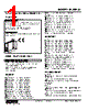
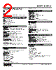
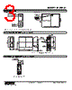
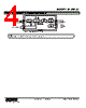

Understanding the Schematic and "Option" Labels
The schematic and its accompanying text use DIP switch positions labeled 1-8. It's designed around a base socket to enable more flexible options, but the core functions of the device are controlled by the DIP Switches.
️· DIP Switch 1: "Isolation" - The effect of this switch isn't explained other than to be an option.
️· DIP Switch 2: "Memory" - likely referring to a memory function within the amplifier.
️· DIP Switch 5: "Low Drift Amplifier" - Suggests the amplifier's performance characteristics are altered based on this setting.
️· DIP Switch 8: "Output Driver" - Likely impacts the signal output stage.
Important Considerations
️· Default State: The schematic doesn't specify the default (ON/OFF) state of the DIP switches. You would need to consult the device's full documentation or datasheet to determine this.
️· Combinations: The 'Option' descriptions indicate that the functions aren't activated individually, rather they are combined. It's likely that different combinations of DIP switch settings can produce different amplifier behaviours.
Disclaimer
This is an interpretation based solely on the provided text and schematic. The actual behaviour of the device will depend on the specific design and implementation. Always refer to the official documentation for accurate and complete information.
Understanding the Schematic and "Option" Labels
The schematic and its accompanying text use DIP switch positions labeled 1-8. It's designed around a base socket to enable more flexible options, but the core functions of the device are controlled by the DIP Switches.
️· DIP Switch 1: "Isolation" - The effect of this switch isn't explained other than to be an option.
️· DIP Switch 2: "Memory" - likely referring to a memory function within the amplifier.
️· DIP Switch 5: "Low Drift Amplifier" - Suggests the amplifier's performance characteristics are altered based on this setting.
️· DIP Switch 8: "Output Driver" - Likely impacts the signal output stage.
Important Considerations
️· Default State: The schematic doesn't specify the default (ON/OFF) state of the DIP switches. You would need to consult the device's full documentation or datasheet to determine this.
️· Combinations: The 'Option' descriptions indicate that the functions aren't activated individually, rather they are combined. It's likely that different combinations of DIP switch settings can produce different amplifier behaviours.
Disclaimer
This is an interpretation based solely on the provided text and schematic. The actual behaviour of the device will depend on the specific design and implementation. Always refer to the official documentation for accurate and complete information.
| Part No. | M2AMS2-3A-R2/N |
| Manufacturer | MSYSTEM |
| Size | 116 Kbytes |
| Pages | 4 pages |
| Description | Super-mini Signal Conditioners Mini-M Series |
| Does ALLDATASHEET help your business so far? [ DONATE ] |
About Alldatasheet | Advertisement | Contact us | Privacy Policy | Link to Datasheet | Link Exchange | Manufacturer List All Rights Reserved©Alldatasheet.com |
| Russian : Alldatasheetru.com | Korean : Alldatasheet.co.kr | Spanish : Alldatasheet.es | French : Alldatasheet.fr | Italian : Alldatasheetit.com Portuguese : Alldatasheetpt.com | Polish : Alldatasheet.pl | Vietnamese : Alldatasheet.vn Indian : Alldatasheet.in | Mexican : Alldatasheet.com.mx | British : Alldatasheet.co.uk | New Zealand : Alldatasheet.co.nz |
|
Family Site : ic2ic.com |
icmetro.com |
 British ▼
  English
 Chinese
 German
 Japanese
 Russian
 Korean
 Spanish
 French
 Italian
 Portuguese
 Polish
 Vietnamese
 Indian
 Mexican
 New Zealand