 |
Electronic Components Datasheet Search |
|
|
Electronic Components Datasheet Search |
|
The question interval is too short.
Please try again in a few seconds.

Hello, Please ask a question about JR-45-C/BL Datasheet
# Example questions:
➢ What is the purpose of the burnout/isolation feature and how does it relate to signal transmission?
➢ What is its function in relation to this module?
➢ What are the available output types or signal ranges for this module, as indicated in the documentation?
| Part No. | JR-45-C/BL |
| Manufacturer | MSYSTEM |
| Size | 99 Kbytes |
| Pages | 3 pages |
| Description | Plug-in Signal Conditioners M-UNIT |

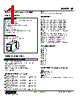
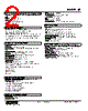
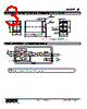

Okay, let's break down this extensive documentation for the JR module. Here's a consolidated summary, categorized for clarity, along with key takeaways:
1. General Identification & Purpose:
️· Product: JR Module (likely a process indicator or controller)
️· Function: This is a digital module designed for process monitoring and control. It takes sensor inputs and outputs signals, often for display or control actions.
️· Manufacturer: M-System (implied from the URL and references)
️· Documentation Revision: Revision 10 (as indicated by the file name)
2. Technical Specifications & Features (Key Highlights):
️· Input/Output: Seems to support both analog and digital inputs/outputs. The schematic diagram shows connections for power, input, and output signals.
️· Communication: Capable of serial communication (likely RS-485 or similar), as indicated by the "modular jack" and "serial transmission line" labels.
️· Burnout Isolation: The module incorporates burnout isolation, which enhances reliability by preventing faults from affecting other connected devices.
️· Low Drift Digital Output: The digital output signals exhibit low drift, which is crucial for accurate measurements and control actions.
️· Modular Design: The module's design allows for integration with other modules (PU-2x)
️· Digital Signal Processing: The module's complexity is demonstrated with terms like "Amplifier Computation Driver" indicating a processor for the signal.
3. Physical Dimensions & Mounting:
️· Dimensions: The drawings show the physical layout and dimensions. Note the "no extra space needed between units" comment indicating a modular, compact design.
️· Mounting: Designed for DIN rail mounting.
4. Wiring & Connections:
️· Schematic Diagram: Provides a detailed schematic, showing pin assignments, power connections, input signals (U(+), V(-)), and output connections. This is *essential* for proper wiring.
️· Pin Labels: Pin labels (1, 5, 5, 8) associated with specific functions like power, inputs, and serial communication.
️· Terminal Design: Clamp terminals shown for wiring.
5. Important Notes & Cautions:
️· Wiring: Refer to the schematic diagram for correct wiring. Incorrect wiring can damage the module.
️· Physical Installation: Follow mounting instructions to ensure proper installation and avoid damage.
️· Compatibility: When integrating with other modules (PU-2x), ensure compatibility.
Let me know if you have any specific questions about a particular aspect of this documentation!
1. General Identification & Purpose:
️· Product: JR Module (likely a process indicator or controller)
️· Function: This is a digital module designed for process monitoring and control. It takes sensor inputs and outputs signals, often for display or control actions.
️· Manufacturer: M-System (implied from the URL and references)
️· Documentation Revision: Revision 10 (as indicated by the file name)
2. Technical Specifications & Features (Key Highlights):
️· Input/Output: Seems to support both analog and digital inputs/outputs. The schematic diagram shows connections for power, input, and output signals.
️· Communication: Capable of serial communication (likely RS-485 or similar), as indicated by the "modular jack" and "serial transmission line" labels.
️· Burnout Isolation: The module incorporates burnout isolation, which enhances reliability by preventing faults from affecting other connected devices.
️· Low Drift Digital Output: The digital output signals exhibit low drift, which is crucial for accurate measurements and control actions.
️· Modular Design: The module's design allows for integration with other modules (PU-2x)
️· Digital Signal Processing: The module's complexity is demonstrated with terms like "Amplifier Computation Driver" indicating a processor for the signal.
3. Physical Dimensions & Mounting:
️· Dimensions: The drawings show the physical layout and dimensions. Note the "no extra space needed between units" comment indicating a modular, compact design.
️· Mounting: Designed for DIN rail mounting.
4. Wiring & Connections:
️· Schematic Diagram: Provides a detailed schematic, showing pin assignments, power connections, input signals (U(+), V(-)), and output connections. This is *essential* for proper wiring.
️· Pin Labels: Pin labels (1, 5, 5, 8) associated with specific functions like power, inputs, and serial communication.
️· Terminal Design: Clamp terminals shown for wiring.
5. Important Notes & Cautions:
️· Wiring: Refer to the schematic diagram for correct wiring. Incorrect wiring can damage the module.
️· Physical Installation: Follow mounting instructions to ensure proper installation and avoid damage.
️· Compatibility: When integrating with other modules (PU-2x), ensure compatibility.
| Part No. | JR-45-C/BL |
| Manufacturer | MSYSTEM |
| Size | 99 Kbytes |
| Pages | 3 pages |
| Description | Plug-in Signal Conditioners M-UNIT |
| Does ALLDATASHEET help your business so far? [ DONATE ] |
About Alldatasheet | Advertisement | Contact us | Privacy Policy | Link to Datasheet | Link Exchange | Manufacturer List All Rights Reserved©Alldatasheet.com |
| Russian : Alldatasheetru.com | Korean : Alldatasheet.co.kr | Spanish : Alldatasheet.es | French : Alldatasheet.fr | Italian : Alldatasheetit.com Portuguese : Alldatasheetpt.com | Polish : Alldatasheet.pl | Vietnamese : Alldatasheet.vn Indian : Alldatasheet.in | Mexican : Alldatasheet.com.mx | British : Alldatasheet.co.uk | New Zealand : Alldatasheet.co.nz |
|
Family Site : ic2ic.com |
icmetro.com |
 British ▼
  English
 Chinese
 German
 Japanese
 Russian
 Korean
 Spanish
 French
 Italian
 Portuguese
 Polish
 Vietnamese
 Indian
 Mexican
 New Zealand