 |
Electronic Components Datasheet Search |
|
|
Electronic Components Datasheet Search |
|
The question interval is too short.
Please try again in a few seconds.

Hello, Please ask a question about LMBT5087LT1 Datasheet
# Example questions:
➢ Referring to figure 14, describe what the graph represents and how it can be used in thermal design.
➢ How does the noise figure change as the collector current increases?
➢ What two parameters are crucial for calculating the peak rise in junction temperature when dealing with pulsed power dissipation?
| Part No. | LMBT5087LT1 |
| Manufacturer | LRC |
| Size | 144 Kbytes |
| Pages | 6 pages |
| Description | Low Noise Transistor |




1. General Information:
️· Type: PNP Bipolar Junction Transistor (BJT)
️· Manufacturer: Leshan Radio Company (implied by the "Leshan Radio Company" branding)
️· Application: Suitable for low-noise amplifier applications (explicitly mentioned).
️· Datasheet ID: Implied: This is an excerpt from a larger datasheet.
2. Electrical Characteristics:
️· Polarity: PNP
️· Key Parameters (From datasheet excerpts):
- Noise Figure: The datasheet emphasizes low noise characteristics, with figures and contours provided (see "Noise Characteristics" section below).
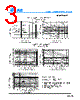
- Thermal Response: Design note explains how to use Figure 14 (Thermal Response) to calculate junction temperature rise under pulsed power conditions.
3. Noise Characteristics:
️· Noise Voltage (e<sub>n</sub>): The noise voltage of the transistor. Referenced in Figure 3.
️· Noise Current (i<sub>n</sub>): The noise current of the transistor. Referenced in Figure 4.
️· Source Resistance (R<sub>s</sub>): The resistance of the source. Used in the noise figure calculation.
️· Noise Figure (NF): The crucial parameter for amplifiers. The formula for calculation is given:
```
NF = 20 log10 ( –––––––––––––––)
(e n [2] + 4KTR S + I n2 R S2)
```
Where:
- `K` is Boltzmann's Constant (1.38 x 10<sup>-23</sup> j/°K)
- `T` is the temperature of the Source Resistance (°K)
- Figures 3, 3 and 5 graphically illustrate noise characteristics and noise figure contours vs. collector current.
4. Dynamic Characteristics:
️· Turn-On Time: Illustrated in Figure 10.
️· Turn-Off Time: Illustrated in Figure 11.
️· Current-Gain - Bandwidth Product (h<sub>FE</sub>·f<sub>T</sub>): Illustrated in Figure 12.
️· Reverse Voltage: Illustrated in Figure 13.
️· Capacitance: Illustrated in Figure 13.
️· Thermal Response: Figure 14 shows thermal response curves.
5. Design Note & Thermal Considerations:
️· Transient Thermal Resistance (Z θJA(t)): A key design parameter. Calculated as the value from Figure 14 multiplied by the steady-state thermal resistance (R θJA).
️· Example Calculation: Shows how to calculate the peak junction temperature rise (∆T) for a specific pulsed power scenario (2.0W, t1=1.0ms, t2=5.0ms, D=0.2) resulting in a ∆T of 88°C.
️· Reference: Design note references document "AN-569" for more details.
6. Figures and Their Content:
️· Figure 1: Noise Voltage (vs. frequency)
️· Figure 2: Noise Current (vs. frequency)
️· Figure 3: Noise Voltage (vs. Collector Current)
️· Figure 4: Noise Current (vs. Collector Current)
️· Figure 5: Noise Figure Contours (vs. Collector Current)
️· Figure 6: Collector Saturation Region (graph)
️· Figure 7: Collector Characteristics (graph)
️· Figure 10: Turn-On Time (graph)
️· Figure 11: Turn-Off Time (graph)
️· Figure 12: Current-Gain – Bandwidth Product (graph)
️· Figure 13: Capacitance and Reverse Voltage (graph)
️· Figure 14: Thermal Response (graph)
️· Figure 15: Typical Collector Leakage Current (graph)
1. General Information:
️· Type: PNP Bipolar Junction Transistor (BJT)
️· Manufacturer: Leshan Radio Company (implied by the "Leshan Radio Company" branding)
️· Application: Suitable for low-noise amplifier applications (explicitly mentioned).
️· Datasheet ID: Implied: This is an excerpt from a larger datasheet.
2. Electrical Characteristics:
️· Polarity: PNP
️· Key Parameters (From datasheet excerpts):
- Noise Figure: The datasheet emphasizes low noise characteristics, with figures and contours provided (see "Noise Characteristics" section below).
- Thermal Response: Design note explains how to use Figure 14 (Thermal Response) to calculate junction temperature rise under pulsed power conditions.
3. Noise Characteristics:
️· Noise Voltage (e<sub>n</sub>): The noise voltage of the transistor. Referenced in Figure 3.
️· Noise Current (i<sub>n</sub>): The noise current of the transistor. Referenced in Figure 4.
️· Source Resistance (R<sub>s</sub>): The resistance of the source. Used in the noise figure calculation.
️· Noise Figure (NF): The crucial parameter for amplifiers. The formula for calculation is given:
```
NF = 20 log10 ( –––––––––––––––)
(e n [2] + 4KTR S + I n2 R S2)
```
Where:
- `K` is Boltzmann's Constant (1.38 x 10<sup>-23</sup> j/°K)
- `T` is the temperature of the Source Resistance (°K)
- Figures 3, 3 and 5 graphically illustrate noise characteristics and noise figure contours vs. collector current.
4. Dynamic Characteristics:
️· Turn-On Time: Illustrated in Figure 10.
️· Turn-Off Time: Illustrated in Figure 11.
️· Current-Gain - Bandwidth Product (h<sub>FE</sub>·f<sub>T</sub>): Illustrated in Figure 12.
️· Reverse Voltage: Illustrated in Figure 13.
️· Capacitance: Illustrated in Figure 13.
️· Thermal Response: Figure 14 shows thermal response curves.
5. Design Note & Thermal Considerations:
️· Transient Thermal Resistance (Z θJA(t)): A key design parameter. Calculated as the value from Figure 14 multiplied by the steady-state thermal resistance (R θJA).
️· Example Calculation: Shows how to calculate the peak junction temperature rise (∆T) for a specific pulsed power scenario (2.0W, t1=1.0ms, t2=5.0ms, D=0.2) resulting in a ∆T of 88°C.
️· Reference: Design note references document "AN-569" for more details.
6. Figures and Their Content:
️· Figure 1: Noise Voltage (vs. frequency)
️· Figure 2: Noise Current (vs. frequency)
️· Figure 3: Noise Voltage (vs. Collector Current)
️· Figure 4: Noise Current (vs. Collector Current)
️· Figure 5: Noise Figure Contours (vs. Collector Current)
️· Figure 6: Collector Saturation Region (graph)
️· Figure 7: Collector Characteristics (graph)
️· Figure 10: Turn-On Time (graph)
️· Figure 11: Turn-Off Time (graph)
️· Figure 12: Current-Gain – Bandwidth Product (graph)
️· Figure 13: Capacitance and Reverse Voltage (graph)
️· Figure 14: Thermal Response (graph)
️· Figure 15: Typical Collector Leakage Current (graph)
| Part No. | LMBT5087LT1 |
| Manufacturer | LRC |
| Size | 144 Kbytes |
| Pages | 6 pages |
| Description | Low Noise Transistor |
| Does ALLDATASHEET help your business so far? [ DONATE ] |
About Alldatasheet | Advertisement | Contact us | Privacy Policy | Link to Datasheet | Link Exchange | Manufacturer List All Rights Reserved©Alldatasheet.com |
| Russian : Alldatasheetru.com | Korean : Alldatasheet.co.kr | Spanish : Alldatasheet.es | French : Alldatasheet.fr | Italian : Alldatasheetit.com Portuguese : Alldatasheetpt.com | Polish : Alldatasheet.pl | Vietnamese : Alldatasheet.vn Indian : Alldatasheet.in | Mexican : Alldatasheet.com.mx | British : Alldatasheet.co.uk | New Zealand : Alldatasheet.co.nz |
|
Family Site : ic2ic.com |
icmetro.com |
 British ▼
  English
 Chinese
 German
 Japanese
 Russian
 Korean
 Spanish
 French
 Italian
 Portuguese
 Polish
 Vietnamese
 Indian
 Mexican
 New Zealand