 |
Electronic Components Datasheet Search |
|
|
Electronic Components Datasheet Search |
|
The question interval is too short.
Please try again in a few seconds.

Hello, Please ask a question about TB67S279FTG Datasheet
# Example questions:
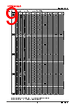
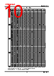
➢ What happens when the step resolution is set to 1/4 step?
➢ What is the relationship between the 'iouta (%)' and 'ioutb (%)' values and the maximum current setting when step resolution is set to 1/1 or 1/2(a)?
➢ If the electrical angle is at 180 degrees, and the step resolution is set to 1/16, what is the approximate iouta (%) value?
| Part No. | TB67S279FTG |
| Manufacturer | TOSHIBA |
| Size | 459 Kbytes |
| Pages | 27 pages |
| Description | Active Gain Control Clock-in control Bipolar stepping motor driver |


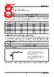


# TB67S279FTG Stepping Motor Driver
## Features
️· Type: Clock-in controlled bipolar stepping motor driver
️· Active Gain Control (AGC): Built-in anti-stall architecture.
️· ACDS: Sense resistor less current control.
️· Rds(on): 0.6Ω (High + Low side).
️· Micro-stepping: Full, Half(a), Half(b), Quarter, 1/8, 1/16, 1/32 step resolutions.
️· Error Detection: Thermal shutdown (TSD), Over current detection (ISD), Power-on-reset (POR), Motor load open (OPD).
️· Error Output: Flags error states.
️· Internal Regulator: 5V regulator allows single power supply operation.
️· Adjustable PWM: Adjustable constant current PWM frequency via external components.
️· Package: QFN48 (7.0mm x 7.0mm) with thermal pad.
️· Ratings: 50V, 2.0A
## Pinout (Key Pins)
️· AGC0, AGC1: Active Gain Control setup pins.
️· CLIM0, CLIM1: AGC current limiter setup pins.
️· DMODE0, DMODE1, DMODE2: Step resolution setting pins.
️· CLK: Step clock input.
️· ENABLE: Motor output ON/OFF.
️· RESET: Electrical angle initialization.
️· VMA, VMB: Motor power supply inputs.
️· OUTA+, OUTA-, OUTB+, OUTB-: Motor outputs.
️· GND: Ground.
️· VCC: Internal regulator monitor.
## Functional Description
️· AGC: Reduces current during stall conditions to prevent motor stopping.
️· ACDS: Controls motor current without external sense resistors.
️· Micro-stepping: Allows for smooth and precise motor control.
️· Error Detection: Protects the driver and motor from faults.
️· Adjustable PWM: Allows customization of the PWM frequency for different applications.
## Electrical Characteristics
️· Supply Voltage: 50V max
️· Output Current: 2.0A
️· Rds(on): 0.6Ω
️· VCC Voltage: 5V (internal regulator)
## Application Notes
️· Thermal Management: Consider heat dissipation during operation.
️· PCB Layout: Solder corner pad and thermal pad to GND plane.
️· Component Selection: Use appropriate external components for PWM frequency adjustment.
# TB67S279FTG Stepping Motor Driver
## Features
️· Type: Clock-in controlled bipolar stepping motor driver
️· Active Gain Control (AGC): Built-in anti-stall architecture.
️· ACDS: Sense resistor less current control.
️· Rds(on): 0.6Ω (High + Low side).
️· Micro-stepping: Full, Half(a), Half(b), Quarter, 1/8, 1/16, 1/32 step resolutions.
️· Error Detection: Thermal shutdown (TSD), Over current detection (ISD), Power-on-reset (POR), Motor load open (OPD).
️· Error Output: Flags error states.
️· Internal Regulator: 5V regulator allows single power supply operation.
️· Adjustable PWM: Adjustable constant current PWM frequency via external components.
️· Package: QFN48 (7.0mm x 7.0mm) with thermal pad.
️· Ratings: 50V, 2.0A
## Pinout (Key Pins)
️· AGC0, AGC1: Active Gain Control setup pins.
️· CLIM0, CLIM1: AGC current limiter setup pins.
️· DMODE0, DMODE1, DMODE2: Step resolution setting pins.
️· CLK: Step clock input.
️· ENABLE: Motor output ON/OFF.
️· RESET: Electrical angle initialization.
️· VMA, VMB: Motor power supply inputs.
️· OUTA+, OUTA-, OUTB+, OUTB-: Motor outputs.
️· GND: Ground.
️· VCC: Internal regulator monitor.
## Functional Description
️· AGC: Reduces current during stall conditions to prevent motor stopping.
️· ACDS: Controls motor current without external sense resistors.
️· Micro-stepping: Allows for smooth and precise motor control.
️· Error Detection: Protects the driver and motor from faults.
️· Adjustable PWM: Allows customization of the PWM frequency for different applications.
## Electrical Characteristics
️· Supply Voltage: 50V max
️· Output Current: 2.0A
️· Rds(on): 0.6Ω
️· VCC Voltage: 5V (internal regulator)
## Application Notes
️· Thermal Management: Consider heat dissipation during operation.
️· PCB Layout: Solder corner pad and thermal pad to GND plane.
️· Component Selection: Use appropriate external components for PWM frequency adjustment.
| Part No. | TB67S279FTG |
| Manufacturer | TOSHIBA |
| Size | 459 Kbytes |
| Pages | 27 pages |
| Description | Active Gain Control Clock-in control Bipolar stepping motor driver |
| Does ALLDATASHEET help your business so far? [ DONATE ] |
About Alldatasheet | Advertisement | Contact us | Privacy Policy | Link to Datasheet | Link Exchange | Manufacturer List All Rights Reserved©Alldatasheet.com |
| Russian : Alldatasheetru.com | Korean : Alldatasheet.co.kr | Spanish : Alldatasheet.es | French : Alldatasheet.fr | Italian : Alldatasheetit.com Portuguese : Alldatasheetpt.com | Polish : Alldatasheet.pl | Vietnamese : Alldatasheet.vn Indian : Alldatasheet.in | Mexican : Alldatasheet.com.mx | British : Alldatasheet.co.uk | New Zealand : Alldatasheet.co.nz |
|
Family Site : ic2ic.com |
icmetro.com |
 British ▼
  English
 Chinese
 German
 Japanese
 Russian
 Korean
 Spanish
 French
 Italian
 Portuguese
 Polish
 Vietnamese
 Indian
 Mexican
 New Zealand