 |
Electronic Components Datasheet Search |
|
|
Electronic Components Datasheet Search |
|
The question interval is too short.
Please try again in a few seconds.

Hello, Please ask a question about TJA1081 Datasheet
# Example questions:
➢ Describe the conditions under which the tja1081 transceiver will enter sleep mode, referencing specific flags or voltage conditions.
➢ Explain how the tja1081 transceiver handles a wake-up event triggered by a dedicated flexray data frame versus a local wake-up event via the wake pin.
➢ What are the primary differences between sleep mode and standby mode for the tja1081 transceiver?
| Part No. | TJA1081 |
| Manufacturer | NXP |
| Size | 187 Kbytes |
| Pages | 36 pages |
| Description | FlexRay node transceiver |






1. Overall System & Operating Modes
️· Purpose: The TJA1081 is a FlexRay node transceiver. FlexRay is a communication standard used in automotive and industrial applications requiring reliable, time-triggered communication.
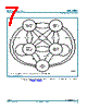
️· Operating Modes: The TJA1081 has several power-saving modes:
- Receive-Only: Transmitter disabled, only receives data.
- Standby: Low power, monitors the bus for wake-up patterns. Receiver is activated to monitor.
- Go-to-Sleep: Similar to Standby. After a certain amount of time (go-to-sleep hold time), it enters Sleep mode even if wake flag is not cleared.
- Sleep: Lowest power mode. Pin INH (which controls the driver) is floating.
️· Mode Switching: The active mode is determined by the voltage levels on pins EN (Enable) and STBN (Standby).
️· Fail-Silent Behavior: The system is designed to fail safely – to enter a defined state if power or other conditions become unstable.
2. Wake-Up Mechanisms
️· Purpose: Allows the device to transition from low-power modes to active communication.
️· Types:
- Remote Wake-Up (Bus Wake-Up):
■ Wake-Up Pattern: Recognizes specific sequences of data bits (DATA_0 and DATA_1) on the FlexRay bus.
■ Dedicated FlexRay Data Frame: Detects a specially formatted data frame to trigger a wake-up. The Byte Start Sequences (BSS) are interruptions to the data pattern that need to be accounted for.
- Local Wake-Up (Pin WAKE): Triggered by a voltage on the WAKE pin being below a threshold for a specified time.
️· Wake Flag: A key internal signal that indicates a wake-up event has occurred.
- Sets pin INH (switches it on).
- Affects which mode the device enters after a wake-up.
️· RXD & RXEN: Driven LOW if the wake flag is set.
3. Undervoltage Protection & Fail-Safe Behavior
️· Purpose: To ensure safe operation and predictable behavior under low-voltage conditions.
️· Undervoltage Flags: Internal flags (UV VBAT, UV VCC, UV VIO) are set when the voltage on the respective pins (V BAT, V CC, V IO) falls below their undervoltage detection thresholds.
️· Behavior with Undervoltage:
- UV VBAT: Enters Sleep mode (lowest power).
- UV VCC: Enters Standby mode.
- UV VIO: Sets internal pins (EN, STBN, TXD, BGE low, TXEN high) and can enter sleep mode.
️· Reset Mechanism: When power fails, a reset signal is triggered to the digital state machine to ensure a defined state.
4. Key Pins & Their Functions
️· EN (Enable): Determines the operating mode, in conjunction with STBN.
️· STBN (Standby): Determines the operating mode, in conjunction with EN.
️· INH (Driver Enable): Controls the driver (transceiver). Set HIGH to enable the driver, low to disable.
️· WAKE: External pin for local wake-up events.
️· V BAT, V CC, V IO: Power supply pins.
️· TXD, BGE, TXEN: Related to transmitter function.
️· RXD, RXEN: Related to receiver function.
5. Flags Explained
️· Local Wake-up Source Flag: Indicates a wake-up event occurred on the WAKE pin. It's reset when entering a low power mode.
1. Overall System & Operating Modes
️· Purpose: The TJA1081 is a FlexRay node transceiver. FlexRay is a communication standard used in automotive and industrial applications requiring reliable, time-triggered communication.
️· Operating Modes: The TJA1081 has several power-saving modes:
- Receive-Only: Transmitter disabled, only receives data.
- Standby: Low power, monitors the bus for wake-up patterns. Receiver is activated to monitor.
- Go-to-Sleep: Similar to Standby. After a certain amount of time (go-to-sleep hold time), it enters Sleep mode even if wake flag is not cleared.
- Sleep: Lowest power mode. Pin INH (which controls the driver) is floating.
️· Mode Switching: The active mode is determined by the voltage levels on pins EN (Enable) and STBN (Standby).
️· Fail-Silent Behavior: The system is designed to fail safely – to enter a defined state if power or other conditions become unstable.
2. Wake-Up Mechanisms
️· Purpose: Allows the device to transition from low-power modes to active communication.
️· Types:
- Remote Wake-Up (Bus Wake-Up):
■ Wake-Up Pattern: Recognizes specific sequences of data bits (DATA_0 and DATA_1) on the FlexRay bus.
■ Dedicated FlexRay Data Frame: Detects a specially formatted data frame to trigger a wake-up. The Byte Start Sequences (BSS) are interruptions to the data pattern that need to be accounted for.
- Local Wake-Up (Pin WAKE): Triggered by a voltage on the WAKE pin being below a threshold for a specified time.
️· Wake Flag: A key internal signal that indicates a wake-up event has occurred.
- Sets pin INH (switches it on).
- Affects which mode the device enters after a wake-up.
️· RXD & RXEN: Driven LOW if the wake flag is set.
3. Undervoltage Protection & Fail-Safe Behavior
️· Purpose: To ensure safe operation and predictable behavior under low-voltage conditions.
️· Undervoltage Flags: Internal flags (UV VBAT, UV VCC, UV VIO) are set when the voltage on the respective pins (V BAT, V CC, V IO) falls below their undervoltage detection thresholds.
️· Behavior with Undervoltage:
- UV VBAT: Enters Sleep mode (lowest power).
- UV VCC: Enters Standby mode.
- UV VIO: Sets internal pins (EN, STBN, TXD, BGE low, TXEN high) and can enter sleep mode.
️· Reset Mechanism: When power fails, a reset signal is triggered to the digital state machine to ensure a defined state.
4. Key Pins & Their Functions
️· EN (Enable): Determines the operating mode, in conjunction with STBN.
️· STBN (Standby): Determines the operating mode, in conjunction with EN.
️· INH (Driver Enable): Controls the driver (transceiver). Set HIGH to enable the driver, low to disable.
️· WAKE: External pin for local wake-up events.
️· V BAT, V CC, V IO: Power supply pins.
️· TXD, BGE, TXEN: Related to transmitter function.
️· RXD, RXEN: Related to receiver function.
5. Flags Explained
️· Local Wake-up Source Flag: Indicates a wake-up event occurred on the WAKE pin. It's reset when entering a low power mode.
| Part No. | TJA1081 |
| Manufacturer | NXP |
| Size | 187 Kbytes |
| Pages | 36 pages |
| Description | FlexRay node transceiver |
| Does ALLDATASHEET help your business so far? [ DONATE ] |
About Alldatasheet | Advertisement | Contact us | Privacy Policy | Link to Datasheet | Link Exchange | Manufacturer List All Rights Reserved©Alldatasheet.com |
| Russian : Alldatasheetru.com | Korean : Alldatasheet.co.kr | Spanish : Alldatasheet.es | French : Alldatasheet.fr | Italian : Alldatasheetit.com Portuguese : Alldatasheetpt.com | Polish : Alldatasheet.pl | Vietnamese : Alldatasheet.vn Indian : Alldatasheet.in | Mexican : Alldatasheet.com.mx | British : Alldatasheet.co.uk | New Zealand : Alldatasheet.co.nz |
|
Family Site : ic2ic.com |
icmetro.com |
 British ▼
  English
 Chinese
 German
 Japanese
 Russian
 Korean
 Spanish
 French
 Italian
 Portuguese
 Polish
 Vietnamese
 Indian
 Mexican
 New Zealand