 |
Electronic Components Datasheet Search |
|
|
Electronic Components Datasheet Search |
|
The question interval is too short.
Please try again in a few seconds.

Hello, Please ask a question about DS1020-100 Datasheet
# Example questions:
➢ G., tdsc, tdhe). explain what 'tdse' represents and under what conditions it is measured, referencing the document if needed.
➢ What are the key differences between the parallel and serial modes of operation for the ds1020, and when might you choose one over the other?
➢ What is the maximum allowable storage temperature for the ds1020, and what is a potential consequence of exceeding this limit?
| Part No. | DS1020-100 |
| Manufacturer | MAXIM |
| Size | 196 Kbytes |
| Pages | 9 pages |
| Description | Programmable 8-Bit Silicon Delay Line |


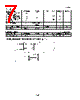
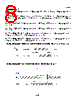


1. Device Overview: Dallas Semiconductor DS1020 Silicon Delay Line
️· Function: This is a programmable silicon delay line, meaning it creates a time delay in a signal. The delay can be adjusted electronically.
️· Modes of Operation: It operates in two main modes:
- Parallel Mode (S=1): Suitable for applications where a single, fixed delay is needed, either non-latched (E=1) or latched.
- Serial Mode (S=0): Used for creating sequences or more complex timing patterns.
2. Electrical Characteristics & Ratings
️· Absolute Maximum Ratings: Define the stress levels the chip can handle without damage. These are not operational limits, but safety margins.
- Voltage on Pins: -1.0V to +7.0V
- Operating Temp: 0°C to 70°C
️· DC Electrical Characteristics: Define typical operating conditions.
- Supply Voltage (VCC): 4.75V - 5.25V
️· AC Electrical Characteristics: Define timing parameters – how fast signals must be, and how long delays are. These are critical for correct device operation. Key parameters include:
- Clock Frequency: Up to 10 MHz
- Data Setup & Hold Times: Critical for serial data integrity.
- Enable Width: The duration the 'Enable' signal must be active.
3. Timing and Delay
️· Delay Measurement: Measured between 1.5V levels of rising/falling edges on input and output signals.
️· Tolerance: Delays are within tolerances outlined in "Table 1" which contains the values of the delay in nanoseconds for various input values.
️· Key Timing Parameters:
- tPLH/tPHL: Input to Output Delay (Rising and Falling edges).
- tWI: Input Pulse Width
- tDSC/tDHC: Data Setup/Hold times for serial mode.
- tPDV/tPDX: Parallel Input Valid to Delay Valid and parallel input change to delay invalid.
4. Test Conditions & Setup
️· Test Environment: Precise temperature (25°C ± 3°C), supply voltage (5V ± 0.1V), controlled input signals.
️· Input Signal: Defined voltage levels (High = 3.0V, Low = 0.0V), impedance (50 ohms max), and rise/fall times (3.0 ns max).
️· Output Loading: Output is loaded with a 74F04 IC.
️· Automated Testing: Uses precision pulse generators, time interval counters, and computer control for automated testing.
5. Key Terminology
️· Period: Time between pulses
️· Pulse Width (tWI): Duration of a pulse.
️· Rise/Fall Times: Time taken for a signal to transition.
️· PLH/PHL: Rise/Fall Time Delay
️· Setup/Hold Times: Critical timing constraints for data validity in serial mode.
Essentially, the document describes a programmable delay line with detailed specifications for electrical characteristics, timing parameters, test conditions, and terminology used.
1. Device Overview: Dallas Semiconductor DS1020 Silicon Delay Line
️· Function: This is a programmable silicon delay line, meaning it creates a time delay in a signal. The delay can be adjusted electronically.
️· Modes of Operation: It operates in two main modes:
- Parallel Mode (S=1): Suitable for applications where a single, fixed delay is needed, either non-latched (E=1) or latched.
- Serial Mode (S=0): Used for creating sequences or more complex timing patterns.
2. Electrical Characteristics & Ratings
️· Absolute Maximum Ratings: Define the stress levels the chip can handle without damage. These are not operational limits, but safety margins.
- Voltage on Pins: -1.0V to +7.0V
- Operating Temp: 0°C to 70°C
️· DC Electrical Characteristics: Define typical operating conditions.
- Supply Voltage (VCC): 4.75V - 5.25V
️· AC Electrical Characteristics: Define timing parameters – how fast signals must be, and how long delays are. These are critical for correct device operation. Key parameters include:
- Clock Frequency: Up to 10 MHz
- Data Setup & Hold Times: Critical for serial data integrity.
- Enable Width: The duration the 'Enable' signal must be active.
3. Timing and Delay
️· Delay Measurement: Measured between 1.5V levels of rising/falling edges on input and output signals.
️· Tolerance: Delays are within tolerances outlined in "Table 1" which contains the values of the delay in nanoseconds for various input values.
️· Key Timing Parameters:
- tPLH/tPHL: Input to Output Delay (Rising and Falling edges).
- tWI: Input Pulse Width
- tDSC/tDHC: Data Setup/Hold times for serial mode.
- tPDV/tPDX: Parallel Input Valid to Delay Valid and parallel input change to delay invalid.
4. Test Conditions & Setup
️· Test Environment: Precise temperature (25°C ± 3°C), supply voltage (5V ± 0.1V), controlled input signals.
️· Input Signal: Defined voltage levels (High = 3.0V, Low = 0.0V), impedance (50 ohms max), and rise/fall times (3.0 ns max).
️· Output Loading: Output is loaded with a 74F04 IC.
️· Automated Testing: Uses precision pulse generators, time interval counters, and computer control for automated testing.
5. Key Terminology
️· Period: Time between pulses
️· Pulse Width (tWI): Duration of a pulse.
️· Rise/Fall Times: Time taken for a signal to transition.
️· PLH/PHL: Rise/Fall Time Delay
️· Setup/Hold Times: Critical timing constraints for data validity in serial mode.
Essentially, the document describes a programmable delay line with detailed specifications for electrical characteristics, timing parameters, test conditions, and terminology used.
| Part No. | DS1020-100 |
| Manufacturer | MAXIM |
| Size | 196 Kbytes |
| Pages | 9 pages |
| Description | Programmable 8-Bit Silicon Delay Line |
| Does ALLDATASHEET help your business so far? [ DONATE ] |
About Alldatasheet | Advertisement | Contact us | Privacy Policy | Link to Datasheet | Link Exchange | Manufacturer List All Rights Reserved©Alldatasheet.com |
| Russian : Alldatasheetru.com | Korean : Alldatasheet.co.kr | Spanish : Alldatasheet.es | French : Alldatasheet.fr | Italian : Alldatasheetit.com Portuguese : Alldatasheetpt.com | Polish : Alldatasheet.pl | Vietnamese : Alldatasheet.vn Indian : Alldatasheet.in | Mexican : Alldatasheet.com.mx | British : Alldatasheet.co.uk | New Zealand : Alldatasheet.co.nz |
|
Family Site : ic2ic.com |
icmetro.com |
 British ▼
  English
 Chinese
 German
 Japanese
 Russian
 Korean
 Spanish
 French
 Italian
 Portuguese
 Polish
 Vietnamese
 Indian
 Mexican
 New Zealand