 |
Electronic Components Datasheet Search |
|
|
Electronic Components Datasheet Search |
|
The question interval is too short.
Please try again in a few seconds.

Hello, Please ask a question about MTD392 Datasheet
# Example questions:
➢ What is the primary function of the 'hbe' pin?
➢ What component value is recommended to be connected across the 'rr+' and 'rr-' pins?
➢ Explain the difference between receiving-mode and transmission-mode collision detection based on the information provided.
| Part No. | MTD392 |
| Manufacturer | ETC |
| Size | 281 Kbytes |
| Pages | 10 pages |
| Description | Coaxial Transceiver Interface |


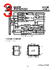


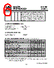


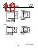

1. Overview & Purpose
️· What They Are: The document describes a series of chips (MTDX92, MTDX93, MTDX94) designed for Ethernet-like network communication. These chips appear to be part of a "MTD392 Technology Family." They're likely intended for early Ethernet implementations (think 10Base2 and 10Base5).
️· Function: These chips act as network interface controllers (NICs) responsible for:
- Transmitting and receiving data.
- Collision detection (critical for shared-medium networks).
- Managing network status indicators.
- Power management
2. Key Features & Concepts
️· Shared Medium Networks: These chips are geared towards networks where all devices share a common cable (like coax cable). This requires careful collision detection to prevent data corruption.
️· Differential Signaling: Many signals (TX+, TX-, RX+, RX-, CD+, CD-, RR+, RR-) are transmitted and received as *differential pairs*. This improves noise immunity.
️· Collision Detection: A *crucial* function. The chips monitor the network for collisions (when two devices try to transmit simultaneously). The `CDS` pin is critical for collision detection – it connects to the coax shield.
️· Heartbeat: A signal (`HBE`) to monitor network health.
️· Test Mode: A specific mode (`TST-` and `MOD-` pins) for testing the device's functionality.
️· Power: Require a negative supply voltage (-9V) with a decoupling capacitor.
️· Open-Drain Outputs: Some outputs (like the status indicator pins) are *open-drain*, meaning they require external pull-up resistors.
3. Pin Descriptions - Highlights
This is a summary of *some* of the key pins. The actual datasheet contains a much more exhaustive list.
️· TX+/TX-: Transmission Data Input - Differential pair for transmitting data.
️· RX+/RX-: Receiving Data Output - Differential pair for receiving data.
️· CDS: Collision Detection Sense - Connects to the network's coax shield for collision detection. A bias network can adjust the detection threshold.
️· CD+/CD-: Collision Output - Differential pair indicating a network collision.
️· TXO: Transmitter Output - Connected to the coax cable via isolation diodes.
️· GND: Ground
️· VEE: Negative Power Supply (-9V)
️· HBE: Heartbeat Enabler
️· TST-/MOD-: Test/Mode pins used to enter test mode or configure the type of collision detection.
️· RR+/RR-: External resistor - requires a 1kΩ resistor across these pins
4. Chip-Specific Differences
️· MTDX92 vs. MTDX93 vs. MTDX94: The chips have slightly different pin layouts and feature sets. Differences are mainly in the implementation of the status indicators, modes of operation, and the position of pins. Refer to the pin diagrams to identify the differences.
️· Early Network Standards: The chips are designed with legacy standards in mind, such as 10Base2 (Thinnet) and 10Base5 (Thicknet).
Important Notes (based on the text):
️· Decoupling Capacitor: Absolutely critical to place a 0.1µF capacitor between GND and VEE, close to the chip.
️· Pull-up Resistors: Open-drain outputs *require* external pull-up resistors.
️· Resistor Network: The CDS pin may require a resistor bias network to fine-tune the collision detection threshold.
️· Isolation Diodes: Ensure you properly isolate the transceiver output to the cable.
1. Overview & Purpose
️· What They Are: The document describes a series of chips (MTDX92, MTDX93, MTDX94) designed for Ethernet-like network communication. These chips appear to be part of a "MTD392 Technology Family." They're likely intended for early Ethernet implementations (think 10Base2 and 10Base5).
️· Function: These chips act as network interface controllers (NICs) responsible for:
- Transmitting and receiving data.
- Collision detection (critical for shared-medium networks).
- Managing network status indicators.
- Power management
2. Key Features & Concepts
️· Shared Medium Networks: These chips are geared towards networks where all devices share a common cable (like coax cable). This requires careful collision detection to prevent data corruption.
️· Differential Signaling: Many signals (TX+, TX-, RX+, RX-, CD+, CD-, RR+, RR-) are transmitted and received as *differential pairs*. This improves noise immunity.
️· Collision Detection: A *crucial* function. The chips monitor the network for collisions (when two devices try to transmit simultaneously). The `CDS` pin is critical for collision detection – it connects to the coax shield.
️· Heartbeat: A signal (`HBE`) to monitor network health.
️· Test Mode: A specific mode (`TST-` and `MOD-` pins) for testing the device's functionality.
️· Power: Require a negative supply voltage (-9V) with a decoupling capacitor.
️· Open-Drain Outputs: Some outputs (like the status indicator pins) are *open-drain*, meaning they require external pull-up resistors.
3. Pin Descriptions - Highlights
This is a summary of *some* of the key pins. The actual datasheet contains a much more exhaustive list.
️· TX+/TX-: Transmission Data Input - Differential pair for transmitting data.
️· RX+/RX-: Receiving Data Output - Differential pair for receiving data.
️· CDS: Collision Detection Sense - Connects to the network's coax shield for collision detection. A bias network can adjust the detection threshold.
️· CD+/CD-: Collision Output - Differential pair indicating a network collision.
️· TXO: Transmitter Output - Connected to the coax cable via isolation diodes.
️· GND: Ground
️· VEE: Negative Power Supply (-9V)
️· HBE: Heartbeat Enabler
️· TST-/MOD-: Test/Mode pins used to enter test mode or configure the type of collision detection.
️· RR+/RR-: External resistor - requires a 1kΩ resistor across these pins
4. Chip-Specific Differences
️· MTDX92 vs. MTDX93 vs. MTDX94: The chips have slightly different pin layouts and feature sets. Differences are mainly in the implementation of the status indicators, modes of operation, and the position of pins. Refer to the pin diagrams to identify the differences.
️· Early Network Standards: The chips are designed with legacy standards in mind, such as 10Base2 (Thinnet) and 10Base5 (Thicknet).
Important Notes (based on the text):
️· Decoupling Capacitor: Absolutely critical to place a 0.1µF capacitor between GND and VEE, close to the chip.
️· Pull-up Resistors: Open-drain outputs *require* external pull-up resistors.
️· Resistor Network: The CDS pin may require a resistor bias network to fine-tune the collision detection threshold.
️· Isolation Diodes: Ensure you properly isolate the transceiver output to the cable.
| Part No. | MTD392 |
| Manufacturer | ETC |
| Size | 281 Kbytes |
| Pages | 10 pages |
| Description | Coaxial Transceiver Interface |
| Does ALLDATASHEET help your business so far? [ DONATE ] |
About Alldatasheet | Advertisement | Contact us | Privacy Policy | Link to Datasheet | Link Exchange | Manufacturer List All Rights Reserved©Alldatasheet.com |
| Russian : Alldatasheetru.com | Korean : Alldatasheet.co.kr | Spanish : Alldatasheet.es | French : Alldatasheet.fr | Italian : Alldatasheetit.com Portuguese : Alldatasheetpt.com | Polish : Alldatasheet.pl | Vietnamese : Alldatasheet.vn Indian : Alldatasheet.in | Mexican : Alldatasheet.com.mx | British : Alldatasheet.co.uk | New Zealand : Alldatasheet.co.nz |
|
Family Site : ic2ic.com |
icmetro.com |
 British ▼
  English
 Chinese
 German
 Japanese
 Russian
 Korean
 Spanish
 French
 Italian
 Portuguese
 Polish
 Vietnamese
 Indian
 Mexican
 New Zealand