 |
Electronic Components Datasheet Search |
|
|
Electronic Components Datasheet Search |
|
The question interval is too short.
Please try again in a few seconds.

Hello, Please ask a question about 8340-G210-R1H2 Datasheet
# Example questions:
➢ What are the available options for the 'terminal design' of the circuit breaker?
➢ Describe the different delay options available for the 'characteristic curve'?
➢ What are the possible configurations for 'auxiliary contacts', and what does '1 pair n/c (11/12)' signify?
| Part No. | 8340-G210-R1H2 |
| Manufacturer | ETAL |
| Size | 320 Kbytes |
| Pages | 6 pages |
| Description | Magnetic and Hydraulic-Magnetic Circuit Breaker |

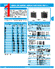
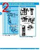




This document describes the specifications for a relay or contactor, likely an overload relay, based on the listed parameters. Here's a breakdown of what it tells us:
1. General Features:
️· Type: Likely a relay or contactor, possibly an overload relay due to parameters like "rated current" and characteristic curves.
️· Functionality: It's a switching device, presumably for controlling circuits based on current or other conditions.
️· Color: The original color was black with a white indicator band, though this may have been changed.
️· Actuator Marking: Has markings indicating the rated current, with a location pin for easy identification of the value.
2. Electrical Characteristics & Options:
️· Rated Current: Available in different ratings as indicated by the "4" or "7" marking.
️· Auxiliary Contacts:
- H0: No auxiliary contacts.
- H1: Includes auxiliary contacts.
- H2: Includes auxiliary contacts, specifically for pole 1.
️· Auxiliary Contact Function: The aux contacts offer two possible functions:
- 1: One normally open (NO) and one normally closed (NC) contact.
- 3: One pair of normally closed (NC) contacts.
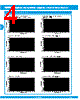
️· Characteristic Curves (Trip Curves): Different curves (e.g., F4, F5, E1, E2, H1, H2, R1, R2) define the tripping behavior of the relay based on current and time. This is essential for overload protection.
️· Current Ratings (Optional): Offers a range of current ratings from 0.02 to 50 Amps.
3. Physical/Mounting Aspects:
️· Thread Size: M12x1 (For mounting)
️· Panel Hardware: Options for securing the relay to a panel.
- "0": No panel hardware
- "1": Includes a hex nut and washer.
4. Terminal Options:
️· P1: Blade terminals (suitable for smaller wires, up to 35 Amps).
️· K4: Screw terminals (suitable for larger wires and higher current ratings).
️· R1: Round connectors.
In short, this document provides a comprehensive list of options and specifications for a switching device, likely used for motor protection or other circuit control applications. It's highly configurable to fit different needs.
1. General Features:
️· Type: Likely a relay or contactor, possibly an overload relay due to parameters like "rated current" and characteristic curves.
️· Functionality: It's a switching device, presumably for controlling circuits based on current or other conditions.
️· Color: The original color was black with a white indicator band, though this may have been changed.
️· Actuator Marking: Has markings indicating the rated current, with a location pin for easy identification of the value.
2. Electrical Characteristics & Options:
️· Rated Current: Available in different ratings as indicated by the "4" or "7" marking.
️· Auxiliary Contacts:
- H0: No auxiliary contacts.
- H1: Includes auxiliary contacts.
- H2: Includes auxiliary contacts, specifically for pole 1.
️· Auxiliary Contact Function: The aux contacts offer two possible functions:
- 1: One normally open (NO) and one normally closed (NC) contact.
- 3: One pair of normally closed (NC) contacts.
️· Characteristic Curves (Trip Curves): Different curves (e.g., F4, F5, E1, E2, H1, H2, R1, R2) define the tripping behavior of the relay based on current and time. This is essential for overload protection.
️· Current Ratings (Optional): Offers a range of current ratings from 0.02 to 50 Amps.
3. Physical/Mounting Aspects:
️· Thread Size: M12x1 (For mounting)
️· Panel Hardware: Options for securing the relay to a panel.
- "0": No panel hardware
- "1": Includes a hex nut and washer.
4. Terminal Options:
️· P1: Blade terminals (suitable for smaller wires, up to 35 Amps).
️· K4: Screw terminals (suitable for larger wires and higher current ratings).
️· R1: Round connectors.
In short, this document provides a comprehensive list of options and specifications for a switching device, likely used for motor protection or other circuit control applications. It's highly configurable to fit different needs.
| Part No. | 8340-G210-R1H2 |
| Manufacturer | ETAL |
| Size | 320 Kbytes |
| Pages | 6 pages |
| Description | Magnetic and Hydraulic-Magnetic Circuit Breaker |
| Does ALLDATASHEET help your business so far? [ DONATE ] |
About Alldatasheet | Advertisement | Contact us | Privacy Policy | Link to Datasheet | Link Exchange | Manufacturer List All Rights Reserved©Alldatasheet.com |
| Russian : Alldatasheetru.com | Korean : Alldatasheet.co.kr | Spanish : Alldatasheet.es | French : Alldatasheet.fr | Italian : Alldatasheetit.com Portuguese : Alldatasheetpt.com | Polish : Alldatasheet.pl | Vietnamese : Alldatasheet.vn Indian : Alldatasheet.in | Mexican : Alldatasheet.com.mx | British : Alldatasheet.co.uk | New Zealand : Alldatasheet.co.nz |
|
Family Site : ic2ic.com |
icmetro.com |
 British ▼
  English
 Chinese
 German
 Japanese
 Russian
 Korean
 Spanish
 French
 Italian
 Portuguese
 Polish
 Vietnamese
 Indian
 Mexican
 New Zealand