|
Electronic Components Datasheet Search |
|
|
Electronic Components Datasheet Search |
|
STM32F412RGH7P Datasheet(PDF) 110 Page - STMicroelectronics |
|
|
|||||||||||||||||||||||||||||
STM32F412RGH7P Datasheet(HTML) 110 Page - STMicroelectronics |
|
|
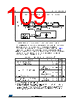
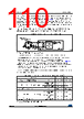
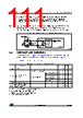
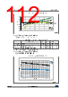
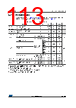
110 / 201 page 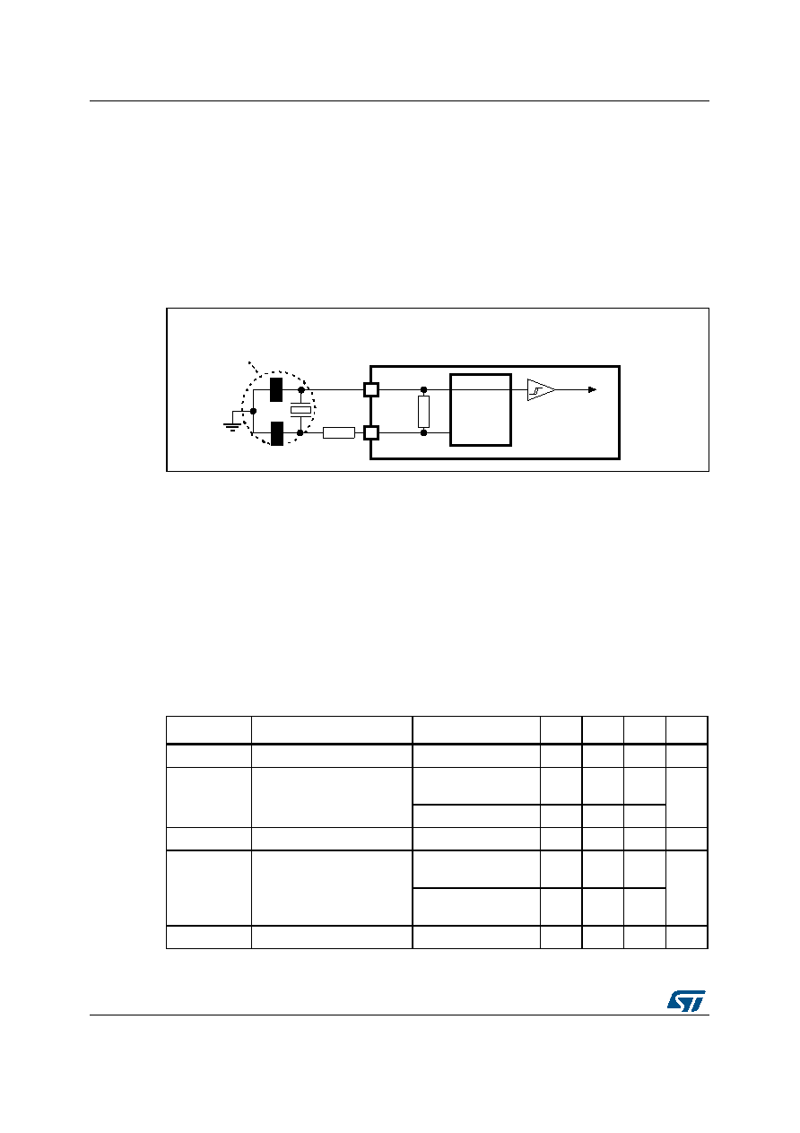 Electrical characteristics STM32F412xE/G 110/201 DocID028087 Rev 7 For CL1 and CL2, it is recommended to use high-quality external ceramic capacitors in the 5 pF to 25 pF range (Typ.), designed for high-frequency applications, and selected to match the requirements of the crystal or resonator (see Figure 29). CL1 and CL2 are usually the same size. The crystal manufacturer typically specifies a load capacitance which is the series combination of CL1 and CL2. PCB and MCU pin capacitance must be included (10 pF can be used as a rough estimate of the combined pin and board capacitance) when sizing CL1 and CL2. Note: For information on selecting the crystal, refer to the application note AN2867 “Oscillator design guide for ST microcontrollers” available from the ST website www.st.com. Figure 29. Typical application with an 8 MHz crystal 1. REXT value depends on the crystal characteristics. Low-speed external clock generated from a crystal/ceramic resonator The low-speed external (LSE) clock can be supplied with a 32.768 kHz crystal/ceramic resonator oscillator. All the information given in this paragraph are based on characterization results obtained with typical external components specified in Table 42. In the application, the resonator and the load capacitors have to be placed as close as possible to the oscillator pins in order to minimize output distortion and startup stabilization time. Refer to the crystal resonator manufacturer for more details on the resonator characteristics (frequency, package, accuracy). The LSE high-power mode allows to cover a wider range of possible crystals but with a cost of higher power consumption. Table 42. LSE oscillator characteristics (fLSE = 32.768 kHz) (1) 1. Guaranteed by design, not tested in production. Symbol Parameter Conditions Min Typ Max Unit RF Feedback resistor - - 18.4 - M Ω IDD LSE current consumption Low-power mode (default) -- 1 µA High-drive mode - - 3 ACCLSE(2) LSE accuracy - -500 - 500 ppm Gm_crit_max Maximum critical crystal gm Startup, low-power mode -- 0.56 µA/V Startup, high-drive mode -- 1.50 tSU(LSE)(3) startup time VDD is stabilized - 2 - s |
|
Link URL |
| Does ALLDATASHEET help your business so far? [ DONATE ] |
About Alldatasheet | Advertisement | Contact us | Privacy Policy | Link to Datasheet | Link Exchange | Manufacturer List All Rights Reserved©Alldatasheet.com |
| Russian : Alldatasheetru.com | Korean : Alldatasheet.co.kr | Spanish : Alldatasheet.es | French : Alldatasheet.fr | Italian : Alldatasheetit.com Portuguese : Alldatasheetpt.com | Polish : Alldatasheet.pl | Vietnamese : Alldatasheet.vn Indian : Alldatasheet.in | Mexican : Alldatasheet.com.mx | British : Alldatasheet.co.uk | New Zealand : Alldatasheet.co.nz |
|
Family Site : ic2ic.com |
icmetro.com |
 British ▼
 English
 Chinese
 German
 Japanese
 Russian
 Korean
 Spanish
 French
 Italian
 Portuguese
 Polish
 Vietnamese
 Indian
 Mexican
 British
 New Zealand