|
Electronic Components Datasheet Search |
|
|
Electronic Components Datasheet Search |
|
H8SX/1663R Datasheet(PDF) 1249 Page - Renesas Technology Corp |
|
|
|||||||||||||||||||||||||||||
H8SX/1663R Datasheet(HTML) 1249 Page - Renesas Technology Corp |
|
|
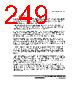
1249 / 1504 page  Section 26 Boundary Scan Rev. 2.00 Sep. 24, 2008 Page 1217 of 1468 REJ09B0412-0200 26.5.2 Commands BYPASS (Instruction Code: B'1111): The BYPASS instruction is an instruction that drives the bypass register (JTBPR). This instruction shortens the shift path, facilitating the transfer of serial data to other LSIs on a printed-circuit board at higher speeds. While this instruction is being executed, the test circuit has no effect on the system circuits. The bypass register (JTBPR) is connected between the TDI and TDO pins. Bypass operation is initiated from shift-DR operation. The TDO is at 0 in the first clock cycle in the shift-DR state; in the subsequent clock cycles, the TDI signal is output on the TDO pin. EXTEST (Instruction Code: B'0000): The EXTEST instruction is used to test external circuits when this LSI is installed on the printed circuit board. If this instruction is executed, output pins are used to output test data (specified by the SAMPLE/PRELOAD instruction) from the boundary scan register to the print circuit board, and input pins are used to input test result. SAMPLE/PRELOAD (Instruction Code: B'0100): The SAMPLE/PRELOAD instruction is used to input data from the LSI internal circuits to the boundary scan register, output data from scan path, and reload the data to the scan path. While this instruction is executed, input signals are directly input to the LSI and output signals are also directly output to the external circuits. The LSI system circuit is not affected by this function. In SAMPLE operation, the boundary scan register latches the snap shot of data transferred from input pins to internal circuit or data transferred from internal circuit to output pins. The latched data is read from the scan path. The scan register latches the snap data at the rising edge of the TCK in Capture-DR state. The scan register latches snap shot without affecting the LSI normal operation. In PRELOAD operation, initial value is written from the scan path to the parallel output latch of the boundary scan register prior to the EXTEST instruction execution. If the EXTEST is executed without executing this PRELOAD operation, undefined values are output from the beginning to the end (transfer to the output latch) of the EXTEST sequence. (In EXTEST instruction, output parallel latches are always output to the output pins.) IDCODE (Instruction Code: B'0001): When the IDCODE instruction is selected, IDCODE register value is output to the TDO in Shift-DR state of the TAP controller. In this case, IDCODE register value is output from the LSB. During this instruction execution, test circuit does not affect the system circuit. INSTR is initialized by the IDCODE instruction in Test-Logic-Reset state of the TAP controller. |
|
Link URL |
| Does ALLDATASHEET help your business so far? [ DONATE ] |
About Alldatasheet | Advertisement | Contact us | Privacy Policy | Link to Datasheet | Link Exchange | Manufacturer List All Rights Reserved©Alldatasheet.com |
| Russian : Alldatasheetru.com | Korean : Alldatasheet.co.kr | Spanish : Alldatasheet.es | French : Alldatasheet.fr | Italian : Alldatasheetit.com Portuguese : Alldatasheetpt.com | Polish : Alldatasheet.pl | Vietnamese : Alldatasheet.vn Indian : Alldatasheet.in | Mexican : Alldatasheet.com.mx | British : Alldatasheet.co.uk | New Zealand : Alldatasheet.co.nz |
|
Family Site : ic2ic.com |
icmetro.com |
 British ▼
 English
 Chinese
 German
 Japanese
 Russian
 Korean
 Spanish
 French
 Italian
 Portuguese
 Polish
 Vietnamese
 Indian
 Mexican
 British
 New Zealand