 |
Electronic Components Datasheet Search |
|
|
Electronic Components Datasheet Search |
|
The question interval is too short.
Please try again in a few seconds.

Hello, Please ask a question about AMIS-42675 Datasheet
# Example questions:
➢ What is the recommended maximum junction temperature (tj) before the amis-42675 initiates thermal shutdown?
➢ What is the por (power on reset) level required for the canh, canl, and vref pins to transition to a tri-state condition?
➢ What are the key considerations when using wave soldering for soic-8 packages with the amis-42675?
| Part No. | AMIS-42675 |
| Manufacturer | AMI |
| Size | 565 Kbytes |
| Pages | 12 pages |
| Description | High-Speed Low Power CAN Transceiver |





1. Overview & Purpose
️· Device: AMIS-42675
️· Type: High-Speed Low Power CAN Transceiver
️· Purpose: Designed for CAN (Controller Area Network) communication, commonly used in automotive, industrial, and other applications requiring robust, reliable data transfer. This transceiver provides the physical layer interface for CAN buses.
️· Key Features Highlighted: Low power consumption, high speed, isolation, and suitability for long networks.
2. Functional Description
️· CAN Protocol: Compliant with CAN specifications (ISO 11898).
️· Differential Signaling: Uses differential signals (CANH and CANL) for improved noise immunity.
️· Data Transmission & Reception: Handles both transmitting and receiving CAN messages.
️· Isolation: Offers galvanic isolation, preventing ground loops and protecting circuits from voltage differences.
️· Fault Tolerance: Includes features for fault detection and handling (e.g., thermal shutdown, fault flags).
️· Wake-Up Functionality: Can be put into a low-power sleep mode and woken up by bus activity.
3. Electrical Characteristics (Key Parameters & Meanings)
This is a *very* long list in the original document. Here are some highlights and explanations of key parameters:
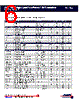
️· Supply Voltage (Vdd): The voltage required to power the device (typically 3.3V or 5V - see datasheet for specific ranges).
️· Common-Mode Voltage Range (Vcm): The range of voltage differences between CANH and CANL that the device can handle without malfunction. This is crucial for noise immunity.
️· Differential Input Thresholds (VID): The voltage difference needed to register a logic '1' or '0' on the CAN bus.
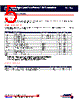
️· Propagation Delays (td(TxD-BUSon), td(BUSoff-RXD), etc.): These define how long it takes for signals to propagate through the device. Lower values are generally better for high-speed communication. (TxD = Transmit Data, RXD = Receive Data, BUSon/off = Bus Active/Inactive).
️· Timing Parameters: These dictate the speed and synchronization of the CAN communication. (e.g., td(stb-nm) delay standby mode to normal mode).
️· Fault Flags (ERR_REC, ERR_DOM): These output signals indicate the presence of errors detected during transmission or reception.
️· Common-Mode Transient Immunity (CMI): A measure of the device's ability to withstand voltage spikes on the CAN bus without causing errors.
️· Thermal Shutdown Temperature (Tj(sd)): The temperature at which the device will shut down to prevent damage from overheating.
4. Functional Diagram & Pinout
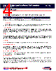
️· Pinout: A detailed description of each pin and its function (e.g., Vdd, GND, CANH, CANL, TXD, RXD, STB, NM).
️· Functional Diagram: Illustrates the internal architecture of the transceiver.
5. Measurement Set-ups
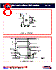
️· Describes how the electrical characteristics were measured, including the test equipment and circuit configurations used.
6. Package Information
️· Package Types: Available in SOIC-8 (Small Outline Integrated Circuit, 8-lead) package.
️· Package Dimensions: Provides detailed dimensions for the SOIC-8 package.
️· Soldering Information: (See Below)
7. Soldering Information
️· General Guidance: Provides advice on both re-flow and wave soldering techniques.
️· Re-flow Soldering: Preferred method, especially for fine-pitch packages. Specifies temperature profiles and cautions about moisture sensitivity.
️· Wave Soldering: Not recommended for all package types or pitches. Requires specific techniques like double-wave soldering and solder thieves to prevent shorts.
️· Manual Soldering: Detailed instructions for manual soldering with low-voltage soldering irons.
Important Notes & Cautions (from the document):
️· Moisture Sensitivity: Surface mount devices (SMDs) are sensitive to moisture. Proper handling and drying procedures are required to prevent damage.
️· Soldering Process: The soldering process is critical for reliable performance. Follow the recommended guidelines carefully.
️· Package Handling: Handle the device and package with care to avoid physical damage.
️· Galvanic Isolation: Maintain proper isolation precautions to ensure safety and prevent ground loops.
This summary attempts to capture the essence of the AMIS-42675 datasheet. The complete document should be consulted for detailed specifications, diagrams, and application notes.
1. Overview & Purpose
️· Device: AMIS-42675
️· Type: High-Speed Low Power CAN Transceiver
️· Purpose: Designed for CAN (Controller Area Network) communication, commonly used in automotive, industrial, and other applications requiring robust, reliable data transfer. This transceiver provides the physical layer interface for CAN buses.
️· Key Features Highlighted: Low power consumption, high speed, isolation, and suitability for long networks.
2. Functional Description
️· CAN Protocol: Compliant with CAN specifications (ISO 11898).
️· Differential Signaling: Uses differential signals (CANH and CANL) for improved noise immunity.
️· Data Transmission & Reception: Handles both transmitting and receiving CAN messages.
️· Isolation: Offers galvanic isolation, preventing ground loops and protecting circuits from voltage differences.
️· Fault Tolerance: Includes features for fault detection and handling (e.g., thermal shutdown, fault flags).
️· Wake-Up Functionality: Can be put into a low-power sleep mode and woken up by bus activity.
3. Electrical Characteristics (Key Parameters & Meanings)
This is a *very* long list in the original document. Here are some highlights and explanations of key parameters:
️· Supply Voltage (Vdd): The voltage required to power the device (typically 3.3V or 5V - see datasheet for specific ranges).
️· Common-Mode Voltage Range (Vcm): The range of voltage differences between CANH and CANL that the device can handle without malfunction. This is crucial for noise immunity.
️· Differential Input Thresholds (VID): The voltage difference needed to register a logic '1' or '0' on the CAN bus.
️· Propagation Delays (td(TxD-BUSon), td(BUSoff-RXD), etc.): These define how long it takes for signals to propagate through the device. Lower values are generally better for high-speed communication. (TxD = Transmit Data, RXD = Receive Data, BUSon/off = Bus Active/Inactive).
️· Timing Parameters: These dictate the speed and synchronization of the CAN communication. (e.g., td(stb-nm) delay standby mode to normal mode).
️· Fault Flags (ERR_REC, ERR_DOM): These output signals indicate the presence of errors detected during transmission or reception.
️· Common-Mode Transient Immunity (CMI): A measure of the device's ability to withstand voltage spikes on the CAN bus without causing errors.
️· Thermal Shutdown Temperature (Tj(sd)): The temperature at which the device will shut down to prevent damage from overheating.
4. Functional Diagram & Pinout
️· Pinout: A detailed description of each pin and its function (e.g., Vdd, GND, CANH, CANL, TXD, RXD, STB, NM).
️· Functional Diagram: Illustrates the internal architecture of the transceiver.
5. Measurement Set-ups
️· Describes how the electrical characteristics were measured, including the test equipment and circuit configurations used.
6. Package Information
️· Package Types: Available in SOIC-8 (Small Outline Integrated Circuit, 8-lead) package.
️· Package Dimensions: Provides detailed dimensions for the SOIC-8 package.
️· Soldering Information: (See Below)
7. Soldering Information
️· General Guidance: Provides advice on both re-flow and wave soldering techniques.
️· Re-flow Soldering: Preferred method, especially for fine-pitch packages. Specifies temperature profiles and cautions about moisture sensitivity.
️· Wave Soldering: Not recommended for all package types or pitches. Requires specific techniques like double-wave soldering and solder thieves to prevent shorts.
️· Manual Soldering: Detailed instructions for manual soldering with low-voltage soldering irons.
Important Notes & Cautions (from the document):
️· Moisture Sensitivity: Surface mount devices (SMDs) are sensitive to moisture. Proper handling and drying procedures are required to prevent damage.
️· Soldering Process: The soldering process is critical for reliable performance. Follow the recommended guidelines carefully.
️· Package Handling: Handle the device and package with care to avoid physical damage.
️· Galvanic Isolation: Maintain proper isolation precautions to ensure safety and prevent ground loops.
This summary attempts to capture the essence of the AMIS-42675 datasheet. The complete document should be consulted for detailed specifications, diagrams, and application notes.
| Part No. | AMIS-42675 |
| Manufacturer | AMI |
| Size | 565 Kbytes |
| Pages | 12 pages |
| Description | High-Speed Low Power CAN Transceiver |
| Does ALLDATASHEET help your business so far? [ DONATE ] |
About Alldatasheet | Advertisement | Contact us | Privacy Policy | Link to Datasheet | Link Exchange | Manufacturer List All Rights Reserved©Alldatasheet.com |
| Russian : Alldatasheetru.com | Korean : Alldatasheet.co.kr | Spanish : Alldatasheet.es | French : Alldatasheet.fr | Italian : Alldatasheetit.com Portuguese : Alldatasheetpt.com | Polish : Alldatasheet.pl | Vietnamese : Alldatasheet.vn Indian : Alldatasheet.in | Mexican : Alldatasheet.com.mx | British : Alldatasheet.co.uk | New Zealand : Alldatasheet.co.nz |
|
Family Site : ic2ic.com |
icmetro.com |
 British ▼
  English
 Chinese
 German
 Japanese
 Russian
 Korean
 Spanish
 French
 Italian
 Portuguese
 Polish
 Vietnamese
 Indian
 Mexican
 New Zealand