 |
Electronic Components Datasheet Search |
|
|
Electronic Components Datasheet Search |
|
The question interval is too short.
Please try again in a few seconds.

Hello, Please ask a question about USB0403 Datasheet
# Example questions:
➢ What is the primary reason for minimizing the path length between the tvs device and the protected line?
➢ What package type is detailed with dimensional specifications and pad layout in the document?
➢ What are the minimum and maximum dimensions for 'a0' in the tape and reel specifications?
| Part No. | USB0403 |
| Manufacturer | PROTEC |
| Size | 900 Kbytes |
| Pages | 9 pages |
| Description | 350 watt low capacitance tvs array |




1. Overview & Purpose
️· Product: TVS diodes designed for USB and Ethernet port protection. They protect sensitive circuits from voltage transients like ESD (Electrostatic Discharge) and EFT (Electrical Fast Transient).
️· Applications: Primarily aimed at protecting USB 2.0, USB 3.0, and Ethernet ports in a wide range of devices (computers, peripherals, communication equipment, etc.).
️· Key Features (Implied): Fast response time, low clamping voltage, and low leakage current. (These aren't explicitly listed but are typical benefits of TVS diodes.)
2. Electrical Characteristics (Not Fully Detailed in the Provided Snippet)
️· The document would normally include detailed electrical parameters such as:
- Reverse Stand-off Voltage (Vr): The maximum voltage the device can withstand in the reverse direction without breaking down.
- Breakdown Voltage (Vbr): The voltage at which the device starts to conduct significantly.
- Clamping Voltage (Vc): The maximum voltage the device allows to pass through to the protected circuit during a transient event. (Critical parameter)
- Holding Current (Ih): The current the device can handle continuously without being damaged.
- Peak Pulse Power Dissipation (Ppp): The maximum power the device can absorb during a transient pulse.
- Response Time: How quickly the device reacts to a transient.
- Leakage Current: The current that flows through the device when it's in the off state.
3. Application Examples (Figures)
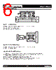
️· USB Protection (Figure 1): Shows the TVS diode connected to the D+ and D- data lines of a USB port. This protects the USB controller from surges. The document suggests using a single bidirectional TVS diode for differential-mode protection.
️· Ethernet Protection (Figure 2): Shows a TVS diode connected to the Rx and Tx lines of an Ethernet transceiver. This protects the transceiver from damage.
️· Circuit Board Recommendations:
- Placement: Place the TVS diode as close as possible to the input connector to minimize trace inductance.
- Trace Length: Minimize the path length between the TVS diode and the protected line.
- Grounding: Use a ground plane and minimize the length of the ground return path.
- Loop Area: Minimize conductive loops (power and ground).
4. Package Information (SOT-143)
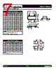
️· Outline Dimensions: Detailed mechanical drawings and dimensions of the SOT-143 package. Includes dimensions for length, width, height, lead spacing, etc.
️· Pad Layout: Recommended PCB pad layout for the SOT-143 package.
5. Tape and Reel Specifications
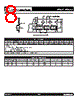
️· Packaging: The TVS diodes are available in tape and reel packaging for automated assembly.
️· Specifications: Detailed dimensions and specifications for the tape and reel packaging. This includes the reel diameter, tape width, component spacing, and other parameters needed for automated pick-and-place machines.
Key takeaways from the document:
1. Overview & Purpose
️· Product: TVS diodes designed for USB and Ethernet port protection. They protect sensitive circuits from voltage transients like ESD (Electrostatic Discharge) and EFT (Electrical Fast Transient).
️· Applications: Primarily aimed at protecting USB 2.0, USB 3.0, and Ethernet ports in a wide range of devices (computers, peripherals, communication equipment, etc.).
️· Key Features (Implied): Fast response time, low clamping voltage, and low leakage current. (These aren't explicitly listed but are typical benefits of TVS diodes.)
2. Electrical Characteristics (Not Fully Detailed in the Provided Snippet)
️· The document would normally include detailed electrical parameters such as:
- Reverse Stand-off Voltage (Vr): The maximum voltage the device can withstand in the reverse direction without breaking down.
- Breakdown Voltage (Vbr): The voltage at which the device starts to conduct significantly.
- Clamping Voltage (Vc): The maximum voltage the device allows to pass through to the protected circuit during a transient event. (Critical parameter)
- Holding Current (Ih): The current the device can handle continuously without being damaged.
- Peak Pulse Power Dissipation (Ppp): The maximum power the device can absorb during a transient pulse.
- Response Time: How quickly the device reacts to a transient.
- Leakage Current: The current that flows through the device when it's in the off state.
3. Application Examples (Figures)
️· USB Protection (Figure 1): Shows the TVS diode connected to the D+ and D- data lines of a USB port. This protects the USB controller from surges. The document suggests using a single bidirectional TVS diode for differential-mode protection.
️· Ethernet Protection (Figure 2): Shows a TVS diode connected to the Rx and Tx lines of an Ethernet transceiver. This protects the transceiver from damage.
️· Circuit Board Recommendations:
- Placement: Place the TVS diode as close as possible to the input connector to minimize trace inductance.
- Trace Length: Minimize the path length between the TVS diode and the protected line.
- Grounding: Use a ground plane and minimize the length of the ground return path.
- Loop Area: Minimize conductive loops (power and ground).
4. Package Information (SOT-143)
️· Outline Dimensions: Detailed mechanical drawings and dimensions of the SOT-143 package. Includes dimensions for length, width, height, lead spacing, etc.
️· Pad Layout: Recommended PCB pad layout for the SOT-143 package.
5. Tape and Reel Specifications
️· Packaging: The TVS diodes are available in tape and reel packaging for automated assembly.
️· Specifications: Detailed dimensions and specifications for the tape and reel packaging. This includes the reel diameter, tape width, component spacing, and other parameters needed for automated pick-and-place machines.
Key takeaways from the document:
| Part No. | USB0403 |
| Manufacturer | PROTEC |
| Size | 900 Kbytes |
| Pages | 9 pages |
| Description | 350 watt low capacitance tvs array |
| Does ALLDATASHEET help your business so far? [ DONATE ] |
About Alldatasheet | Advertisement | Contact us | Privacy Policy | Link to Datasheet | Link Exchange | Manufacturer List All Rights Reserved©Alldatasheet.com |
| Russian : Alldatasheetru.com | Korean : Alldatasheet.co.kr | Spanish : Alldatasheet.es | French : Alldatasheet.fr | Italian : Alldatasheetit.com Portuguese : Alldatasheetpt.com | Polish : Alldatasheet.pl | Vietnamese : Alldatasheet.vn Indian : Alldatasheet.in | Mexican : Alldatasheet.com.mx | British : Alldatasheet.co.uk | New Zealand : Alldatasheet.co.nz |
|
Family Site : ic2ic.com |
icmetro.com |
 British ▼
  English
 Chinese
 German
 Japanese
 Russian
 Korean
 Spanish
 French
 Italian
 Portuguese
 Polish
 Vietnamese
 Indian
 Mexican
 New Zealand