 |
Electronic Components Datasheet Search |
|
|
Electronic Components Datasheet Search |
|
The question interval is too short.
Please try again in a few seconds.

Hello, Please ask a question about SK10LVE111 Datasheet
# Example questions:
➢ What is the typical value for ie (supply current) at 25°c for the pecl dc electrical characteristics?
➢ Compare the minimum value of voh (output high voltage) at -40°c for both ecl and pecl characteristics. what is the difference?
➢ What is the typical value for vbb (reference voltage) at a temperature of 25°c for the pecl dc electrical characteristics?
| Part No. | SK10LVE111 |
| Manufacturer | SEMTECH |
| Size | 150 Kbytes |
| Pages | 6 pages |
| Description | Low Voltage 1:9 Differential ECL/ PECL Clock Driver |


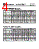
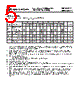


This is a table of electrical characteristics for the SK10LVE111 chip, separated into ECL and PECL modes. Let's break down what's presented and what it means:
Overall Structure
️· Two Sections: The document details characteristics for two modes of operation:
- ECL (Emitter-Coupled Logic): The first set of tables is for operation in ECL mode.
- PECL (Positive Emitter-Coupled Logic): The second set of tables is for operation in PECL mode.
️· Table Format: Each section uses a table to organize the data.
️· Columns: The tables share a consistent structure:
- Symbol: The electrical parameter's abbreviation.
- Characteristic: A description of the parameter being measured.
- TA = -40°C: The parameter's value at a temperature of -40 degrees Celsius.
- Col4, Col5... Col14: Values at varying supply voltages/conditions.
- Unit: The unit of measurement for the parameter (e.g., Volts, Amps, Microamps).
Key Parameters (Examples)
Let's look at a few examples of what these parameters represent:
️· VOH (Output High Voltage): The minimum voltage the output signal will reach when in a high state.
️· VOL (Output Low Voltage): The maximum voltage the output signal will reach when in a low state.
️· VIH (Input High Voltage): The minimum voltage required on an input to be recognized as a high state.
️· VIL (Input Low Voltage): The maximum voltage allowed on an input to be recognized as a low state.
️· VBB (Bias Voltage): The voltage applied to bias the emitter of the transistor.
Important Considerations
️· Temperature: Electrical characteristics change with temperature. The values provided are at specific temperatures (-40°C, 0°C, +25°C, +85°C).
️· Supply Voltage: The chip operates on specific supply voltages. The 'Col4', 'Col5', etc., columns likely represent different supply voltage conditions or test points.
️· Operating Mode: The values are *different* for ECL and PECL modes. It's crucial to use the correct set of values for the operating mode you are using.
️· Absolute Maximum Ratings: This document does *not* include absolute maximum ratings. These ratings define the limits that the chip can withstand without damage. Always consult the full datasheet to understand the absolute maximum ratings.
️· Typical vs. Guaranteed: The values provided may be *typical* values or *guaranteed* values. The datasheet should indicate which is the case. Guaranteed values are those that the manufacturer will ensure the chip meets under all specified conditions.
To fully understand this document, you would need the full datasheet for the SK10LVE111 chip. The datasheet will provide:
️· A complete description of each parameter.
️· Absolute maximum ratings.
️· Recommended operating conditions.
️· Test conditions used to obtain the values in the table.
️· Information on how to interpret the data.
This is a table of electrical characteristics for the SK10LVE111 chip, separated into ECL and PECL modes. Let's break down what's presented and what it means:
Overall Structure
️· Two Sections: The document details characteristics for two modes of operation:
- ECL (Emitter-Coupled Logic): The first set of tables is for operation in ECL mode.
- PECL (Positive Emitter-Coupled Logic): The second set of tables is for operation in PECL mode.
️· Table Format: Each section uses a table to organize the data.
️· Columns: The tables share a consistent structure:
- Symbol: The electrical parameter's abbreviation.
- Characteristic: A description of the parameter being measured.
- TA = -40°C: The parameter's value at a temperature of -40 degrees Celsius.
- Col4, Col5... Col14: Values at varying supply voltages/conditions.
- Unit: The unit of measurement for the parameter (e.g., Volts, Amps, Microamps).
Key Parameters (Examples)
Let's look at a few examples of what these parameters represent:
️· VOH (Output High Voltage): The minimum voltage the output signal will reach when in a high state.
️· VOL (Output Low Voltage): The maximum voltage the output signal will reach when in a low state.
️· VIH (Input High Voltage): The minimum voltage required on an input to be recognized as a high state.
️· VIL (Input Low Voltage): The maximum voltage allowed on an input to be recognized as a low state.
️· VBB (Bias Voltage): The voltage applied to bias the emitter of the transistor.
Important Considerations
️· Temperature: Electrical characteristics change with temperature. The values provided are at specific temperatures (-40°C, 0°C, +25°C, +85°C).
️· Supply Voltage: The chip operates on specific supply voltages. The 'Col4', 'Col5', etc., columns likely represent different supply voltage conditions or test points.
️· Operating Mode: The values are *different* for ECL and PECL modes. It's crucial to use the correct set of values for the operating mode you are using.
️· Absolute Maximum Ratings: This document does *not* include absolute maximum ratings. These ratings define the limits that the chip can withstand without damage. Always consult the full datasheet to understand the absolute maximum ratings.
️· Typical vs. Guaranteed: The values provided may be *typical* values or *guaranteed* values. The datasheet should indicate which is the case. Guaranteed values are those that the manufacturer will ensure the chip meets under all specified conditions.
To fully understand this document, you would need the full datasheet for the SK10LVE111 chip. The datasheet will provide:
️· A complete description of each parameter.
️· Absolute maximum ratings.
️· Recommended operating conditions.
️· Test conditions used to obtain the values in the table.
️· Information on how to interpret the data.
| Part No. | SK10LVE111 |
| Manufacturer | SEMTECH |
| Size | 150 Kbytes |
| Pages | 6 pages |
| Description | Low Voltage 1:9 Differential ECL/ PECL Clock Driver |
| Does ALLDATASHEET help your business so far? [ DONATE ] |
About Alldatasheet | Advertisement | Contact us | Privacy Policy | Link to Datasheet | Link Exchange | Manufacturer List All Rights Reserved©Alldatasheet.com |
| Russian : Alldatasheetru.com | Korean : Alldatasheet.co.kr | Spanish : Alldatasheet.es | French : Alldatasheet.fr | Italian : Alldatasheetit.com Portuguese : Alldatasheetpt.com | Polish : Alldatasheet.pl | Vietnamese : Alldatasheet.vn Indian : Alldatasheet.in | Mexican : Alldatasheet.com.mx | British : Alldatasheet.co.uk | New Zealand : Alldatasheet.co.nz |
|
Family Site : ic2ic.com |
icmetro.com |
 British ▼
  English
 Chinese
 German
 Japanese
 Russian
 Korean
 Spanish
 French
 Italian
 Portuguese
 Polish
 Vietnamese
 Indian
 Mexican
 New Zealand