 |
Electronic Components Datasheet Search |
|
|
Electronic Components Datasheet Search |
|
The question interval is too short.
Please try again in a few seconds.

Hello, Please ask a question about OP4008B Datasheet
# Example questions:
➢ What is the purpose of the metallic center pad on this case and is grounding it optional?
➢ What are the typical vdc and r1 values for a 10k 3v pecl load?
➢ What is the typical 'p' (pitch) value in millimeters?
| Part No. | OP4008B |
| Manufacturer | MURATA |
| Size | 1Mb |
| Pages | 6 pages |
| Description | 669.327 MHz Optical Timing Clock |




1. Device Overview & Purpose
️· Device: OP4008B
️· Type: Surface Mount Crystal Oscillator (SMO)
️· Primary Function: Provides a precise timing reference signal (clock) for electronic circuits, particularly in high-speed digital systems. It's designed for ECL and other fast logic applications.
2. Electrical Characteristics & Key Specifications
️· Single Sideband Phase Noise: The document emphasizes low phase noise, which is critical for maintaining signal integrity in high-speed systems. Specific phase noise figures are detailed in tables (though not fully transcribed here due to their technical nature).
️· Jitter: Jitter is minimized, especially when considering noise on the power supply.
️· Symmetry: The output signals (Q and Q-bar) are designed to be symmetrical.
️· TUNE Input: Provides a way to adjust the oscillation frequency. Not fully detailed.
️· Supply Voltage (VCC): Not explicitly stated but implied to be compatible with ECL voltage levels.
3. Application & Integration
️· ECL Compatibility: Specifically designed to work with ECL (Emitter Coupled Logic) circuits and other high-speed logic families.
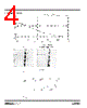
️· Load Termination: The document provides equations and a table to calculate resistor values (R1, R2) for proper load termination when connecting the oscillator output to various ECL loads.
- Formulae (Simplified):
■ `R2 = 50 * V_load / V_dc`
■ `R1 = 1 / (0.02 - (1/R2))`
- Table Examples (for R1 and R2):
■ 10K 3.3V PECL: R1 = 120, R2 = 91
■ 10K 5V PECL: R1 = 240, R2 = 68
️· Negative ECL Loads: The oscillator can drive negative ECL loads by applying a negative voltage to the load points.
4. Physical Characteristics & Packaging
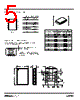
️· Package: SMC-8 (Surface Mount Case - 8-terminal)
️· Case Dimensions: Provided in mm and inches, along with a detailed land pattern for PCB layout.
️· Orientation in Tape Carrier: Covered tape orientation.
️· Quantity per Reel: Varies based on reel size (e.g., 1000 per reel).
️· Carrier Tape Dimensions: Specified for automated assembly.
5. Pinout
️· 1: VCC (Positive Supply)
️· 2: Ground
️· 3: Ground
️· 4: Q Output
️· 5: Q-bar Output
️· 6: Ground
️· 7: Not Defined
️· 8: TUNE Input
️· LID: Ground
Key Takeaways:
️· This device is designed for applications requiring a high-precision, low-noise clock signal.
️· Proper load termination is critical for optimal performance. The provided formulas and table help with this.
️· The SMC-8 package and associated dimensions facilitate automated assembly.
1. Device Overview & Purpose
️· Device: OP4008B
️· Type: Surface Mount Crystal Oscillator (SMO)
️· Primary Function: Provides a precise timing reference signal (clock) for electronic circuits, particularly in high-speed digital systems. It's designed for ECL and other fast logic applications.
2. Electrical Characteristics & Key Specifications
️· Single Sideband Phase Noise: The document emphasizes low phase noise, which is critical for maintaining signal integrity in high-speed systems. Specific phase noise figures are detailed in tables (though not fully transcribed here due to their technical nature).
️· Jitter: Jitter is minimized, especially when considering noise on the power supply.
️· Symmetry: The output signals (Q and Q-bar) are designed to be symmetrical.
️· TUNE Input: Provides a way to adjust the oscillation frequency. Not fully detailed.
️· Supply Voltage (VCC): Not explicitly stated but implied to be compatible with ECL voltage levels.
3. Application & Integration
️· ECL Compatibility: Specifically designed to work with ECL (Emitter Coupled Logic) circuits and other high-speed logic families.
️· Load Termination: The document provides equations and a table to calculate resistor values (R1, R2) for proper load termination when connecting the oscillator output to various ECL loads.
- Formulae (Simplified):
■ `R2 = 50 * V_load / V_dc`
■ `R1 = 1 / (0.02 - (1/R2))`
- Table Examples (for R1 and R2):
■ 10K 3.3V PECL: R1 = 120, R2 = 91
■ 10K 5V PECL: R1 = 240, R2 = 68
️· Negative ECL Loads: The oscillator can drive negative ECL loads by applying a negative voltage to the load points.
4. Physical Characteristics & Packaging
️· Package: SMC-8 (Surface Mount Case - 8-terminal)
️· Case Dimensions: Provided in mm and inches, along with a detailed land pattern for PCB layout.
️· Orientation in Tape Carrier: Covered tape orientation.
️· Quantity per Reel: Varies based on reel size (e.g., 1000 per reel).
️· Carrier Tape Dimensions: Specified for automated assembly.
5. Pinout
️· 1: VCC (Positive Supply)
️· 2: Ground
️· 3: Ground
️· 4: Q Output
️· 5: Q-bar Output
️· 6: Ground
️· 7: Not Defined
️· 8: TUNE Input
️· LID: Ground
Key Takeaways:
️· This device is designed for applications requiring a high-precision, low-noise clock signal.
️· Proper load termination is critical for optimal performance. The provided formulas and table help with this.
️· The SMC-8 package and associated dimensions facilitate automated assembly.
| Part No. | OP4008B |
| Manufacturer | MURATA |
| Size | 1Mb |
| Pages | 6 pages |
| Description | 669.327 MHz Optical Timing Clock |
| Does ALLDATASHEET help your business so far? [ DONATE ] |
About Alldatasheet | Advertisement | Contact us | Privacy Policy | Link to Datasheet | Link Exchange | Manufacturer List All Rights Reserved©Alldatasheet.com |
| Russian : Alldatasheetru.com | Korean : Alldatasheet.co.kr | Spanish : Alldatasheet.es | French : Alldatasheet.fr | Italian : Alldatasheetit.com Portuguese : Alldatasheetpt.com | Polish : Alldatasheet.pl | Vietnamese : Alldatasheet.vn Indian : Alldatasheet.in | Mexican : Alldatasheet.com.mx | British : Alldatasheet.co.uk | New Zealand : Alldatasheet.co.nz |
|
Family Site : ic2ic.com |
icmetro.com |
 British ▼
  English
 Chinese
 German
 Japanese
 Russian
 Korean
 Spanish
 French
 Italian
 Portuguese
 Polish
 Vietnamese
 Indian
 Mexican
 New Zealand