 |
Electronic Components Datasheet Search |
|
|
Electronic Components Datasheet Search |
|
The question interval is too short.
Please try again in a few seconds.

Hello, Please ask a question about OP4018B Datasheet
# Example questions:
➢ Describe the function of terminal 3 on the smc-8 package, and explain what happens if this terminal is activated or deactivated.
➢ What is the nominal operating frequency of the op4018b and what type of oscillator is used to generate this frequency?
➢ What are the minimum and maximum operating ambient temperatures for the op4018b?
| Part No. | OP4018B |
| Manufacturer | MURATA |
| Size | 105 Kbytes |
| Pages | 2 pages |
| Description | 718.864 MHz Optical Timing Clock |


1. Overview & Function
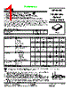
️· Product: OP4018B – A 718.864 MHz optical timing clock. This implies it's generating a precise clock signal for optical communication systems.
️· Technology: SAW (Surface Acoustic Wave) Oscillator. SAW oscillators are known for their frequency stability and precision.
️· Package: SMC-8 (Surface Mount Case - 8-Terminal). This is a compact surface-mount package designed for automated assembly.
️· Application: Primarily used in optical communication equipment where a precise and stable clock is required.
2. Key Specifications & Performance
️· Frequency: 718.864 MHz
️· Operating Voltage (VCC): 3.135 - 3.465 VDC (Nominal 3.3V)
️· Temperature Range: -40°C to +85°C
️· Tune Input Range: Customer-defined range is supported (the part itself has a range, but the customer can exploit more than that)
️· Power Consumption: Approximately 70 mA
️· Enable/Disable: Available via a dedicated Enable/Disable terminal (Pin 3).
3. Pinout & Electrical Connections
️· Pin 1 (VCC): Positive Supply Voltage
️· Pin 2 (Ground): Ground Connection
️· Pin 3 (Enable/Disable): Controls the oscillator's operation (active/inactive).
️· Pin 4 (Q Output): Main clock output signal.
️· Pin 5 (Q Output): Inverted clock output signal (complementary to Q output).
️· Pin 6 (Ground): Ground Connection
️· Pin 7: Unused
️· Pin 8 (Tune Input): Used for frequency adjustment or stabilization (customer specific).
️· LID: Ground connection – crucial for thermal and RF performance.
4. Physical Dimensions & Package Details
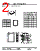
️· SMC-8 Package: Detailed dimensional drawings are provided (A through N) with both millimeter and inch measurements. This is vital for PCB layout and component placement.
️· Lead Finish: Not explicitly stated, but typically would be a tin or tin/lead finish for surface mount applications. (Check with RFM for the exact finish).
5. Important Considerations & Notes
️· Electrostatic Sensitive Device (ESD): Handle with appropriate ESD precautions.
️· Export Restrictions: Requires U.S. Department of Commerce approval for export.
️· RF Performance: Performance is best achieved with proper PCB layout (ground planes, controlled impedance traces), proper termination (50 ohms), and minimizing external noise.
️· Frequency Stability: SAW oscillators are inherently stable, but careful design to minimize environmental influences (temperature, vibration) is important for optimal performance.
️· Linearity The part is designed to be easily tunable beyond nominal values, enabling customer flexibility.
6. Patents
️· The design incorporates elements covered by US patents 4,616,197; 4,670,681; and 4,760,352.
In essence, the RFM OP4018B is a highly precise, surface-mount SAW oscillator designed for optical timing applications, requiring careful handling and layout for optimal RF performance.
1. Overview & Function
️· Product: OP4018B – A 718.864 MHz optical timing clock. This implies it's generating a precise clock signal for optical communication systems.
️· Technology: SAW (Surface Acoustic Wave) Oscillator. SAW oscillators are known for their frequency stability and precision.
️· Package: SMC-8 (Surface Mount Case - 8-Terminal). This is a compact surface-mount package designed for automated assembly.
️· Application: Primarily used in optical communication equipment where a precise and stable clock is required.
2. Key Specifications & Performance
️· Frequency: 718.864 MHz
️· Operating Voltage (VCC): 3.135 - 3.465 VDC (Nominal 3.3V)
️· Temperature Range: -40°C to +85°C
️· Tune Input Range: Customer-defined range is supported (the part itself has a range, but the customer can exploit more than that)
️· Power Consumption: Approximately 70 mA
️· Enable/Disable: Available via a dedicated Enable/Disable terminal (Pin 3).
3. Pinout & Electrical Connections
️· Pin 1 (VCC): Positive Supply Voltage
️· Pin 2 (Ground): Ground Connection
️· Pin 3 (Enable/Disable): Controls the oscillator's operation (active/inactive).
️· Pin 4 (Q Output): Main clock output signal.
️· Pin 5 (Q Output): Inverted clock output signal (complementary to Q output).
️· Pin 6 (Ground): Ground Connection
️· Pin 7: Unused
️· Pin 8 (Tune Input): Used for frequency adjustment or stabilization (customer specific).
️· LID: Ground connection – crucial for thermal and RF performance.
4. Physical Dimensions & Package Details
️· SMC-8 Package: Detailed dimensional drawings are provided (A through N) with both millimeter and inch measurements. This is vital for PCB layout and component placement.
️· Lead Finish: Not explicitly stated, but typically would be a tin or tin/lead finish for surface mount applications. (Check with RFM for the exact finish).
5. Important Considerations & Notes
️· Electrostatic Sensitive Device (ESD): Handle with appropriate ESD precautions.
️· Export Restrictions: Requires U.S. Department of Commerce approval for export.
️· RF Performance: Performance is best achieved with proper PCB layout (ground planes, controlled impedance traces), proper termination (50 ohms), and minimizing external noise.
️· Frequency Stability: SAW oscillators are inherently stable, but careful design to minimize environmental influences (temperature, vibration) is important for optimal performance.
️· Linearity The part is designed to be easily tunable beyond nominal values, enabling customer flexibility.
6. Patents
️· The design incorporates elements covered by US patents 4,616,197; 4,670,681; and 4,760,352.
In essence, the RFM OP4018B is a highly precise, surface-mount SAW oscillator designed for optical timing applications, requiring careful handling and layout for optimal RF performance.
| Part No. | OP4018B |
| Manufacturer | MURATA |
| Size | 105 Kbytes |
| Pages | 2 pages |
| Description | 718.864 MHz Optical Timing Clock |
| Does ALLDATASHEET help your business so far? [ DONATE ] |
About Alldatasheet | Advertisement | Contact us | Privacy Policy | Link to Datasheet | Link Exchange | Manufacturer List All Rights Reserved©Alldatasheet.com |
| Russian : Alldatasheetru.com | Korean : Alldatasheet.co.kr | Spanish : Alldatasheet.es | French : Alldatasheet.fr | Italian : Alldatasheetit.com Portuguese : Alldatasheetpt.com | Polish : Alldatasheet.pl | Vietnamese : Alldatasheet.vn Indian : Alldatasheet.in | Mexican : Alldatasheet.com.mx | British : Alldatasheet.co.uk | New Zealand : Alldatasheet.co.nz |
|
Family Site : ic2ic.com |
icmetro.com |
 British ▼
  English
 Chinese
 German
 Japanese
 Russian
 Korean
 Spanish
 French
 Italian
 Portuguese
 Polish
 Vietnamese
 Indian
 Mexican
 New Zealand