|
Electronic Components Datasheet Search |
|
|
Electronic Components Datasheet Search |
|
OL2385 Datasheet(PDF) 10 Page - NXP Semiconductors |
|
|
|||||||||||||||||||||||||||||
OL2385 Datasheet(HTML) 10 Page - NXP Semiconductors |
|
|
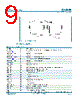
10 / 85 page  OL2385 All information provided in this document is subject to legal disclaimers. © NXP Semiconductors N.V. 2016. All rights reserved. Product data sheet COMPANY PUBLIC Rev. 1.0 — 15 June 2016 10 of 85 NXP Semiconductors OL2385 Industrial RF transceiver [1] Pin TEST must be connected to ground in the application. [2] The exposed die pad area must be connected to ground. [3] VDD_DIGL is the internal supply of the digital part and shall only be externally connected to a blocking capacitor 15 nF (nominal). [4] VDD_DIGL must neither be pulled to high voltages nor to GND [5] Do not use VDD_DIGL to supply external devices [6] All GND_RF are connected internally [7] TXOUT is not to be supplied externally except for an inductor connected to VREGPA [8] RST_N shall be connected only with a 4.7 k Ω resistor in series. [9] MSDA features an on-chip pull-up resistor to VDD_IO and may be left open or terminated to VDD_IO, as desired. [10] MSCL is an output and shall be unconnected in the application. P15 25 GPIO, timer input, timer output, USART0, USART1 P14 26 GPIO, timer output, USART0, USART1 P13 27 GPIO, USART0 P12 28 GPIO, wake-up, timer input, USART0, USART1 P11 29 GPIO, fail safe wake-up, timer input, USART0, USART1 P10 30 GPIO, fail safe wake-up, timer output, RX and TX clock output VDD_IO 31 Power supply for digital I/Os RST_N [8] 32 Reset input (active low), internal pull-up resistor MSDA [9] 33 Monitor and debug interface serial data (input/output; internal pull-up in input mode) MSCL [10] 34 Monitor and debug interface serial clock (output) P17 35 GPIO, wake-up, timer input, timer output, RX data output, TX data input, USART0, USART1 P20 36 GPIO, wake-up, timer output, USART1 P21 37 GPIO, GP ADC input NEG P22 38 GPIO, wake-up, GP ADC input POS, timer output P23 39 GPIO, wake-up, GP ADC reference voltage, USART1 TEST [1] 40 Test pin (must be connected to ground in the application) VDD_DIGL [3][4][5] 41 LDO output voltage GND_DIG 42 Ground (digital) GND_ADC 43 Ground IFN_SENSE_IN 44 Selectable ADC negative input / pin used for test purposes IFP_DCBUS 45 Selectable ADC positive input / pin used for test purposes VDD_ADC 46 Power supply for ADC in receiver chain VDD_RF 47 Power supply for receive path RF_IN_A 48 RF receiver input A (internally multiplexed with RF receiver input B) Table 4. Pinning description Symbol Pin Description |
|
Link URL |
| Does ALLDATASHEET help your business so far? [ DONATE ] |
About Alldatasheet | Advertisement | Contact us | Privacy Policy | Link to Datasheet | Link Exchange | Manufacturer List All Rights Reserved©Alldatasheet.com |
| Russian : Alldatasheetru.com | Korean : Alldatasheet.co.kr | Spanish : Alldatasheet.es | French : Alldatasheet.fr | Italian : Alldatasheetit.com Portuguese : Alldatasheetpt.com | Polish : Alldatasheet.pl | Vietnamese : Alldatasheet.vn Indian : Alldatasheet.in | Mexican : Alldatasheet.com.mx | British : Alldatasheet.co.uk | New Zealand : Alldatasheet.co.nz |
|
Family Site : ic2ic.com |
icmetro.com |
 British ▼
 English
 Chinese
 German
 Japanese
 Russian
 Korean
 Spanish
 French
 Italian
 Portuguese
 Polish
 Vietnamese
 Indian
 Mexican
 British
 New Zealand