|
Electronic Components Datasheet Search |
|
|
Electronic Components Datasheet Search |
|
E39-R12 Datasheet(PDF) 10 Page - Omron Electronics LLC |
|
|
|||||||||||||||||||||||||||||
E39-R12 Datasheet(HTML) 10 Page - Omron Electronics LLC |
|
|
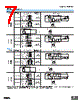
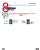
10 / 15 page  E3Z-LT/LR/LL 10 Mounting Direction for Distance-settable Models • Make sure that the sensing side of the Sensor is parallel with the surface of the sensing objects. Normally, do not incline the Sensor towards the sensing object. If the sensing object has a glossy surface, however, incline the Sensor by 5 ° to 10° as shown in the illustration, provided that the Sensor is not influenced by background objects. • If there is a mirror-like object below the Sensor, the Sensor may not operate stably. Therefore, incline the Sensor or separate the Sensor from the mirror-like object as shown below. • Do not install the Sensor in the wrong direction. Refer to the following illustration. Install the Sensor as shown in the following illustration if each sensing object greatly differs in color or material. • The stability indicator may turn off in reaction to reflection from background objects. In such cases, incline the Sensor by 10 ° as shown in the illustration for more stable detection. ● Adjusting Distance-settable Models Indicator Operation Note: If the stability indicator is lit, the detection/no detection status is stable within the rated ambient operating temperature ( −10 to 55 °C). ● Inspection and Maintenance Cleaning Never use paint thinners or other organic solvents to clean the surface of the product. Sensing side Surface of sensing object Glossy object Sensing object Mirror-like object Sensing object Moving direction Moving direction Moving direction Sensing object Sensing object Correct Incorrect Correct Moving direction Moving direction Correct Incorrect Background object, conveyor, etc. Reflection Approx. 10˚ ON OFF ON OFF ON OFF ON OFF Stability (green) Operation (orange) Stability (green) Operation (orange) L/ON D/ON BGS NEAR region Stable NEAR Stable FAR FAR region Unstable NEAR Unstable FAR Distance threshold (settable) |
|
|
Link URL |
| Does ALLDATASHEET help your business so far? [ DONATE ] |
About Alldatasheet | Advertisement | Contact us | Privacy Policy | Link to Datasheet | Link Exchange | Manufacturer List All Rights Reserved©Alldatasheet.com |
| Russian : Alldatasheetru.com | Korean : Alldatasheet.co.kr | Spanish : Alldatasheet.es | French : Alldatasheet.fr | Italian : Alldatasheetit.com Portuguese : Alldatasheetpt.com | Polish : Alldatasheet.pl | Vietnamese : Alldatasheet.vn Indian : Alldatasheet.in | Mexican : Alldatasheet.com.mx | British : Alldatasheet.co.uk | New Zealand : Alldatasheet.co.nz |
|
Family Site : ic2ic.com |
icmetro.com |
 British ▼
 English
 Chinese
 German
 Japanese
 Russian
 Korean
 Spanish
 French
 Italian
 Portuguese
 Polish
 Vietnamese
 Indian
 Mexican
 British
 New Zealand