|
Electronic Components Datasheet Search |
|
|
Electronic Components Datasheet Search |
|
M6NXM-1Z1-R Datasheet(PDF) 1 Page - M-System Co.,Ltd. |
|
|
|||||||||||||||||||||||||||||
M6NXM-1Z1-R Datasheet(HTML) 1 Page - M-System Co.,Ltd. |
|
|
1 / 4 page 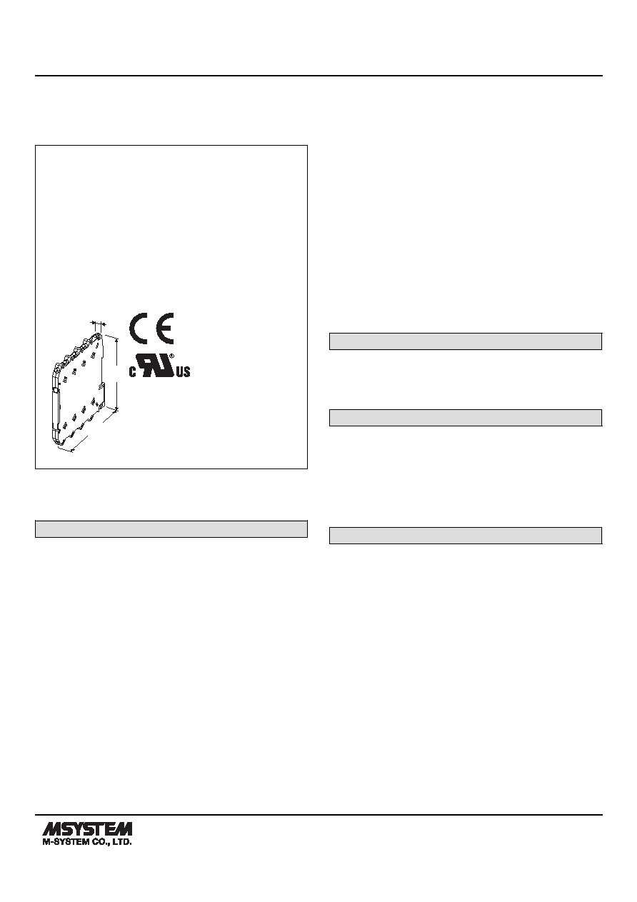 MODEL: M6NXM M6NXM SPECIFICATIONS ES-7909 Rev.10 Page 1/4 http://www.m-system.co.jp/ Screw Terminal Ultra-Slim Signal Conditioners M6N Series POTENTIOMETER TRANSMITTER (PC programmable) Functions & Features • 7.5-mm wide ultra-slim design • Low profile allows the M6N module mounted in a 120-mm deep panel • Provides a DC output proportional to a potentiometer or slidewire position input • Linearization and burnout protection • PC programmable • High-density mounting • Power indicator LED mm (inch) 7.5 (.30) 102 (4.02) 102 (4.02) MODEL: M6NXM–1[1]–R[2] ORDERING INFORMATION • Code number: M6NXM-1[1]-R[2] Specify a code from below for each [1] and [2]. (e.g. M6NXM-1Z1-R/UL/Q) • Potentiometer range (total resistance) (e.g. 0 – 1000 Ω) • Output range (e.g. 4 – 20 mA DC) • Specify the specification for option code /Q (e.g. /C01) INPUT 1: Total resistance 100 – 5000 Ω (Configurator software is used to change the input range.) [1] OUTPUT Current Z1: Range 0 – 20 mA DC Voltage V2: Range -10 – +10 V DC V3: Range -5 – +5 V DC (Configurator software is used to change output over the described range of the selected suffix code. For changing between suffix codes, set the Output Range Selector on the side of unit before software adjustment.) POWER INPUT DC Power R: 24 V DC (Operational voltage range 24 V ±10 %, ripple 10 %p-p max.) [2] OPTIONS (multiple selections) Standards & Approvals blank: CE marking /UL: UL approval, CE marking Other Options blank: none /Q: Option other than the above (specify the specification) SPECIFICATIONS OF OPTION: Q COATING (For the detail, refer to M-System's web site.) /C01: Silicone coating /C02: Polyurethane coating RELATED PRODUCTS • PC configurator software (model: M6CFG) Downloadable at M-System’s web site. A dedicated cable is required to connect the module to the PC. Please refer to the internet software download site or the users manual for the PC configurator for applicable cable types. GENERAL SPECIFICATIONS Connection Input and output: M3 screw terminal (torque 0.5 N·m) Power input: Via the Installation Base (model: M6NBS) or M3 screw terminal (torque 0.5 N·m) Recommended solderless terminal: Max. 5.8 mm (0.23”) wide; Ones with insulation sleeve do not fit. Applicable wire size: 0.2 – 2.5 mm2 Housing material: Flame-resistant resin (black) Isolation: Input to output to power Overrange output: -2 – +102 % (Negative current output is not available.) Zero adjustment: -2 to +2 % (PC programming) Span adjustment: 98 to 102 % (PC programming) Burnout: Upscale standard; downscale or no burnout optional by programming Power LED: Green light turns on when the power is supplied. Status indicator LED: Orange LED; Blinking patterns indicate different operating status of the transmitter. Programming: Downloaded from PC; input type (range), |
Similar Part No. - M6NXM-1Z1-R |
|
Similar Description - M6NXM-1Z1-R |
|
|
|
Link URL |
| Does ALLDATASHEET help your business so far? [ DONATE ] |
About Alldatasheet | Advertisement | Contact us | Privacy Policy | Link to Datasheet | Link Exchange | Manufacturer List All Rights Reserved©Alldatasheet.com |
| Russian : Alldatasheetru.com | Korean : Alldatasheet.co.kr | Spanish : Alldatasheet.es | French : Alldatasheet.fr | Italian : Alldatasheetit.com Portuguese : Alldatasheetpt.com | Polish : Alldatasheet.pl | Vietnamese : Alldatasheet.vn Indian : Alldatasheet.in | Mexican : Alldatasheet.com.mx | British : Alldatasheet.co.uk | New Zealand : Alldatasheet.co.nz |
|
Family Site : ic2ic.com |
icmetro.com |
 British ▼
 English
 Chinese
 German
 Japanese
 Russian
 Korean
 Spanish
 French
 Italian
 Portuguese
 Polish
 Vietnamese
 Indian
 Mexican
 British
 New Zealand