 |
Electronic Components Datasheet Search |
|
|
Electronic Components Datasheet Search |
|
LRP-41MZ-R Datasheet(PDF) 1 Page - M-System Co.,Ltd. |
|
|
|||||||||||||||||||||||||||||
LRP-41MZ-R Datasheet(HTML) 1 Page - M-System Co.,Ltd. |
|
|
1 / 5 page 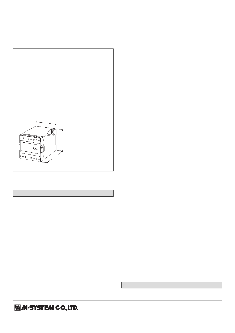 MODEL: LRP http://www.m-system.co.jp/ LRP SPECIFICATIONS ES-1977 Rev.15 Page 1/5 Power Transducer Series L-UNIT VAR TRANSDUCER Functions & Features • Providing a DC output signal in proportion to AC reactive power • DC output containing little ripple is ideal for computer input • "Time division multiplication" method accepts distorted waveforms • Isolation up to 2000 V AC • High-density mounting Typical Applications • Centralized monitoring and control of power management system in a manufacturing facility or building 75 (2.95) 112 (4.41) 75 (2.95) mm (inch) MODEL: LRP–[1][2][3][4]–[5][6] ORDERING INFORMATION • Code number: LRP–[1][2][3][4]-[5][6] Specify a code from below for each [1] through [6]. (e.g. LRP-11PA-C/Q) • Calibration range (e.g. lag 1000 – lead 1000 var) Spacify the range with lag and lead. Don't use plus or minus. • VT ratio, CT ratio (e.g. VT 3300/110 V, CT 250/5 A) • Special output range (For codes Z & 0) • Specify the specification for option code /Q (e.g. /C01/S01) [1] CONFIGURATION 1: 3-phase / 3-wire 4: 3-phase / 4-wire [2] INPUT (unbalanced load) (Voltage must be balanced.) 1: 110 V / 5 A AC 2: 110 V / 1 A AC 3: 220 V / 1 A AC 4: 220 V / 5 A AC 5: 220 V / 380 V / 1 A AC (3-phase / 4-wire) 6: 220 V / 380 V / 5 A AC (3-phase / 4-wire) 7: 110 V / 190 V / 1 A AC (3-phase / 4-wire) 8: 110 V / 190 V / 5 A AC (3-phase / 4-wire) (220 V in code 5 and 6, and 110 V in code 7 and 8 are phase voltage) [3] OUTPUT SIGNAL POLARITY P: Negative in lag, positive in lead M: Negative in lead, positive in lag [4] OUTPUT Current A: 4 – 20 mA DC (Load resistance 600 Ω max.) FW: -10 – +10 mA DC (Load resistance 1000 Ω max.) GW: -1 – +1 mA DC (Load resistance 10 kΩ max.) JW: -5 – +5 mA DC (Load resistance 2000 Ω max.) Z: Specify current (See OUTPUT SPECIFICATIONS) Voltage 6: 1 – 5 V DC (Load resistance 5000 Ω min.) 1W: -10 – +10 mV DC (Load resistance 10 kΩ min.) 2W: -100 – +100 mV DC (Load resistance 100 kΩ min.) 3W: -1 – +1 V DC (Load resistance 1000 Ω min.) 4W: -10 – +10 V DC (Load resistance 10 kΩ min.) 5W: -5 – +5 V DC (Load resistance 5000 Ω min.) 0: Specify voltage (See OUTPUT SPECIFICATIONS) [5] AUXILIARY POWER SUPPLY AC Power B: 100 V AC C: 110 V AC D: 115 V AC F: 120 V AC G: 200 V AC H: 220 V AC J: 240 V AC DC Power R: 24 V DC V: 48 V DC P: 110 V DC [6] OPTIONS blank: none /Q: With options (specify the specification) SPECIFICATIONS OF OPTION: Q (multiple selections) COATING (For the detail, refer to M-System's web site.) /C01: Silicone coating |
Similar Part No. - LRP-41MZ-R |
|
Similar Description - LRP-41MZ-R |
|
|
|
Link URL |
| Does ALLDATASHEET help your business so far? [ DONATE ] |
About Alldatasheet | Advertisement | Contact us | Privacy Policy | Link to Datasheet | Link Exchange | Manufacturer List All Rights Reserved©Alldatasheet.com |
| Russian : Alldatasheetru.com | Korean : Alldatasheet.co.kr | Spanish : Alldatasheet.es | French : Alldatasheet.fr | Italian : Alldatasheetit.com Portuguese : Alldatasheetpt.com | Polish : Alldatasheet.pl | Vietnamese : Alldatasheet.vn Indian : Alldatasheet.in | Mexican : Alldatasheet.com.mx | British : Alldatasheet.co.uk | New Zealand : Alldatasheet.co.nz |
|
Family Site : ic2ic.com |
icmetro.com |
 British ▼
 English
 Chinese
 German
 Japanese
 Russian
 Korean
 Spanish
 French
 Italian
 Portuguese
 Polish
 Vietnamese
 Indian
 Mexican
 British
 New Zealand


