 |
Electronic Components Datasheet Search |
|
|
Electronic Components Datasheet Search |
|
PCF8564A Datasheet(PDF) 24 Page - NXP Semiconductors |
|
|
|||||||||||||||||||||||||||||
PCF8564A Datasheet(HTML) 24 Page - NXP Semiconductors |
|
|
24 / 86 page 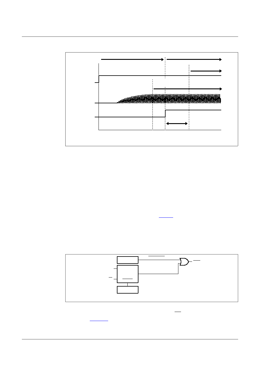 NXP Semiconductors PCA2131 Nano-power highly accurate RTC with integrated quartz crystal for automotive applications aaa-015298 chip in reset chip not in reset chip fully operative t VDD oscillation internal reset OTPR CLKOUT available Figure 9. Dependency between POR and oscillator After POR, the following mode is entered: • 32.768 kHz CLKOUT active • Power-On Reset Override (PORO) available to be set • 24-hour mode is selected • Battery switch-over function disabled, only one power supply (VDD) • Temperature compensation enabled • 100th second enabled • Time 00:00:00.00 • Date 2001.01.01 • Weekday Monday The register values after power-on are shown in Table 4. 7.7.2 Power-On Reset Override (PORO) The POR duration is directly related to the crystal oscillator start-up time. Due to the long start-up times experienced by these types of circuits, a mechanism has been built in to disable the POR and therefore speed up the on-board test of the device. 001aaj324 OSCILLATOR 0 = override inactive 1 = override active 0 = clear override mode 1 = override possible POR_OVRD SDA/CE SCL RESET OVERRIDE CLEAR osc stopped 0 = stopped, 1 = running reset Figure 10. Power-On Reset (POR) system The setting of the PORO mode requires that POR_OVRD in register Control_1 is set logic 1 and that the signals at the interface pins SDA/CE and SCL are toggled as illustrated in Figure 11. All timings shown are required minimum. PCA2131 All information provided in this document is subject to legal disclaimers. © NXP B.V. 2021. All rights reserved. Product data sheet Rev. 1.0 — 26 July 2021 24 / 86 |
|
Link URL |
| Does ALLDATASHEET help your business so far? [ DONATE ] |
About Alldatasheet | Advertisement | Contact us | Privacy Policy | Link to Datasheet | Link Exchange | Manufacturer List All Rights Reserved©Alldatasheet.com |
| Russian : Alldatasheetru.com | Korean : Alldatasheet.co.kr | Spanish : Alldatasheet.es | French : Alldatasheet.fr | Italian : Alldatasheetit.com Portuguese : Alldatasheetpt.com | Polish : Alldatasheet.pl | Vietnamese : Alldatasheet.vn Indian : Alldatasheet.in | Mexican : Alldatasheet.com.mx | British : Alldatasheet.co.uk | New Zealand : Alldatasheet.co.nz |
|
Family Site : ic2ic.com |
icmetro.com |
 British ▼
 English
 Chinese
 German
 Japanese
 Russian
 Korean
 Spanish
 French
 Italian
 Portuguese
 Polish
 Vietnamese
 Indian
 Mexican
 British
 New Zealand


