 |
Electronic Components Datasheet Search |
|
|
Electronic Components Datasheet Search |
|
ATLS25A219D Datasheet(PDF) 13 Page - Analog Technologies, Inc. |
|
|
|||||||||||||||||||||||||||||
ATLS25A219D Datasheet(HTML) 13 Page - Analog Technologies, Inc. |
|
|
13 / 16 page 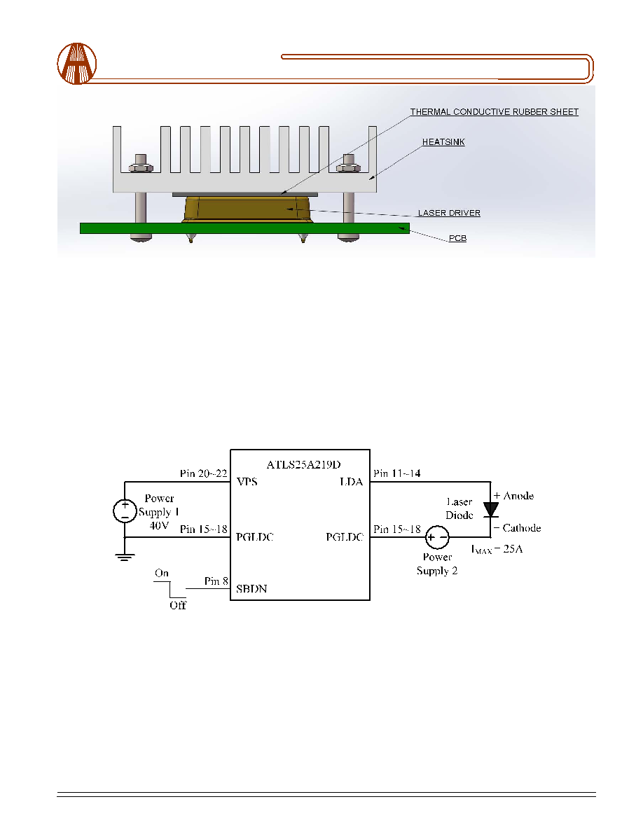 1161 Ringwood Ct, #110, San Jose, CA 95131, U. S. A. Tel.: (408) 748-9100, Fax: (408) 770-9187 www.analogtechnologies.com Copyrights 2000-2022, Analog Technologies, Inc. All Rights Reserved. Updated on 1/24/2022 Email: staff@analogti.com/sales@analogti.com 13 Analog Technologies ATLS25A219D 32V 25A Constant Current Laser Driver Figure 13.2 Transferring Heat with Heat Sink First Time Power Up Laser diode is a high value and vulnerable device. Faults in connections and damages done to the driver during soldering process may damage the laser diode permanently. To protect the laser diode, it is highly recommend to use 3 to 18 regular diodes which is >15A to form a “dummy laser” and insert it in the place of the real laser diode, when powering up the driver for the first time. Use an oscilloscope to monitor the LDA voltage at times of powering up and enabling the shutdown pin, and powering down the laser driver and turning off the shutdown pin, and make sure that there is not over-shoot output voltage at the LDA pin. At the same time, it uses an ammeter in serious with the dummy laser, to make sure that the output current is correct. After thoroughly checking and making sure of free of faults in the system, disconnect the dummy laser diode and connect the real laser diode in place. The driver output voltage range for the laser is between 0.1VVPSto 0.8VVPS (power supply input voltage). Warning: Both the surface mount and the through hole types of packages can only be soldered manually on the board by a solder iron of < 310 °C (590°F), do not use a reflow oven to solder this laser driver. Figure 14. Driving High Voltage Laser Diodes Warning: To turn on the laser, firstly turn on Power Supply 2 and Power Supply 1 while keeping SBDN=0, after >=100mS, then turn on the laser driver ATLS25A219D by using the SBDN pin. To turn off the laser, firstly turn off the laser driver ATLS25A219D by driving the SBDN pin to Standby or Off State, then turn off the Power Supply 2 and 1. |
|
|
Link URL |
| Does ALLDATASHEET help your business so far? [ DONATE ] |
About Alldatasheet | Advertisement | Contact us | Privacy Policy | Link to Datasheet | Link Exchange | Manufacturer List All Rights Reserved©Alldatasheet.com |
| Russian : Alldatasheetru.com | Korean : Alldatasheet.co.kr | Spanish : Alldatasheet.es | French : Alldatasheet.fr | Italian : Alldatasheetit.com Portuguese : Alldatasheetpt.com | Polish : Alldatasheet.pl | Vietnamese : Alldatasheet.vn Indian : Alldatasheet.in | Mexican : Alldatasheet.com.mx | British : Alldatasheet.co.uk | New Zealand : Alldatasheet.co.nz |
|
Family Site : ic2ic.com |
icmetro.com |
 British ▼
 English
 Chinese
 German
 Japanese
 Russian
 Korean
 Spanish
 French
 Italian
 Portuguese
 Polish
 Vietnamese
 Indian
 Mexican
 British
 New Zealand


