 |
Electronic Components Datasheet Search |
|
|
Electronic Components Datasheet Search |
|
SP690TCN Datasheet(PDF) 12 Page - Sipex Corporation |
|
|
|||||||||||||||||||||||||||||
SP690TCN Datasheet(HTML) 12 Page - Sipex Corporation |
|
|
12 / 20 page 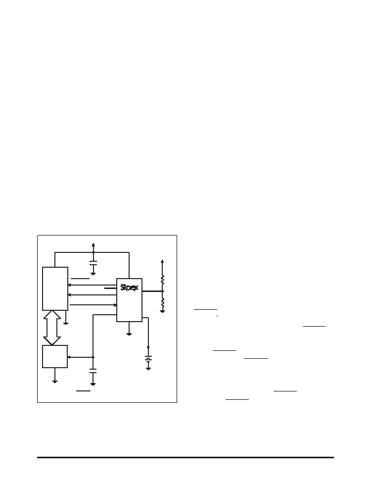 SP690T/S/R JAN 30-06 SP690T/S/R, 802/T/S/R, 804T/S/R, 805T/S/R Low Power Microprocessor Supervisory © 2006 Sipex Corporation 12 THEORY OF OPERATION The SP690T/S/R, SP802T/S/R, SP804T/S/R and SP805T/S/R devices are microprocessor ( µP) supervisory circuits that monitor the power supplied to digital circuits such as microproces- sors, microcontrollers, or memory. The series is an ideal solution for portable, battery-powered equipment that requires power supply monitoring. Implementing this series will reduce the number of components and overall complexity. The watchdog functions of this product family will continuously oversee the operational status of a system. These µP supervisory circuits are not short- circuit protected. Shorting V OUT to ground - excluding power-up transients such as charging a decoupling capacitor - may potentially damage these devices. Decouple both V CC and VBATTERY pins to ground by placing 0.1 µF capacitors as close to the device as possible. The operational features and benefits of the SP690T/S/R, SP802T/S/R, SP804T/S/R and SP805T/S/R devices are described in more detail below. Reset Output The microprocessor's ( µP's) reset input starts the µP in a known state. When the µP is in an unknown state, it should be held in reset. The SP690T/S/R, SP802T/S/R, SP804T/S/R and SP805T/S/R devices assert reset during power-up and prevent code execution errors during power-down or brownout conditions. RESET is guaranteed to be a logic LOW for 0V < V CC < VRST, provided that VBATTERY is greater than 1V. Without a backup battery, RESET is guaranteed valid for V CC > 1V. Once VCC exceeds the reset threshold, an internal timer keeps RESET low for the reset timeout period. After this period, RESET goes HIGH, as seen in Figure 19. If a brownout condition occurs and V CC dips below the reset threshold, RESET goes LOW. Each time RESET is triggered, it stays low for the reset timeout period. Any time V CC goes below the reset threshold, the internal timer restarts. FEATURES The SP690T/S/R, SP802T/S/R, SP804T/S/R and SP805T/S/R devices provide four key functions: 1. A battery backup switch for CMOS RAM, CMOS microprocessors, or other logic. 2. A reset output during power-up, power-down and brownout conditions. 3. A reset pulse if the optional watchdog timer has not been toggled within a specified time. 4. A 1.25V threshold detector for power-fail warning, low battery detection, or to monitor a power supply other than 3.3V or 3.0V. The SP690T/S/R, SP802T/S/R, SP804T/S/R and SP805T/S/R devices differ in their reset- voltage threshold levels and are ideally suited for applications in automotive systems, intelligent instruments, and battery-powered computers and controllers. The series is a solid match for designs where it is critical to monitor the power supply to the µP and it’s related digital components. Figure 20. Typical Operating Circuit GND GND RESET NMI I/O LINE VCC pin 7* PFO WDI VOUT BUS VCC GND VBATTERY R2 R1 Unregulated Regulated +3.3V or +3.0V VCC 0.1 µF PFI DC Lithium Battery 3.6V µP CMOS RAM 0.1 µF RESET for the SP690T/S/R and the SP802T/S/R RESET for the SP804T/S/R and the SP805T/S/R * SP690T/S/R SP802T/S/R SP804T/S/R SP805T/S/R |
|
|
Link URL |
| Does ALLDATASHEET help your business so far? [ DONATE ] |
About Alldatasheet | Advertisement | Contact us | Privacy Policy | Link to Datasheet | Link Exchange | Manufacturer List All Rights Reserved©Alldatasheet.com |
| Russian : Alldatasheetru.com | Korean : Alldatasheet.co.kr | Spanish : Alldatasheet.es | French : Alldatasheet.fr | Italian : Alldatasheetit.com Portuguese : Alldatasheetpt.com | Polish : Alldatasheet.pl | Vietnamese : Alldatasheet.vn Indian : Alldatasheet.in | Mexican : Alldatasheet.com.mx | British : Alldatasheet.co.uk | New Zealand : Alldatasheet.co.nz |
|
Family Site : ic2ic.com |
icmetro.com |
 British ▼
 English
 Chinese
 German
 Japanese
 Russian
 Korean
 Spanish
 French
 Italian
 Portuguese
 Polish
 Vietnamese
 Indian
 Mexican
 British
 New Zealand


