|
Electronic Components Datasheet Search |
|
|
Electronic Components Datasheet Search |
|
E39-R1 Datasheet(PDF) 6 Page - Omron Electronics LLC |
|
|
|||||||||||||||||||||||||||||
E39-R1 Datasheet(HTML) 6 Page - Omron Electronics LLC |
|
|
6 / 10 page 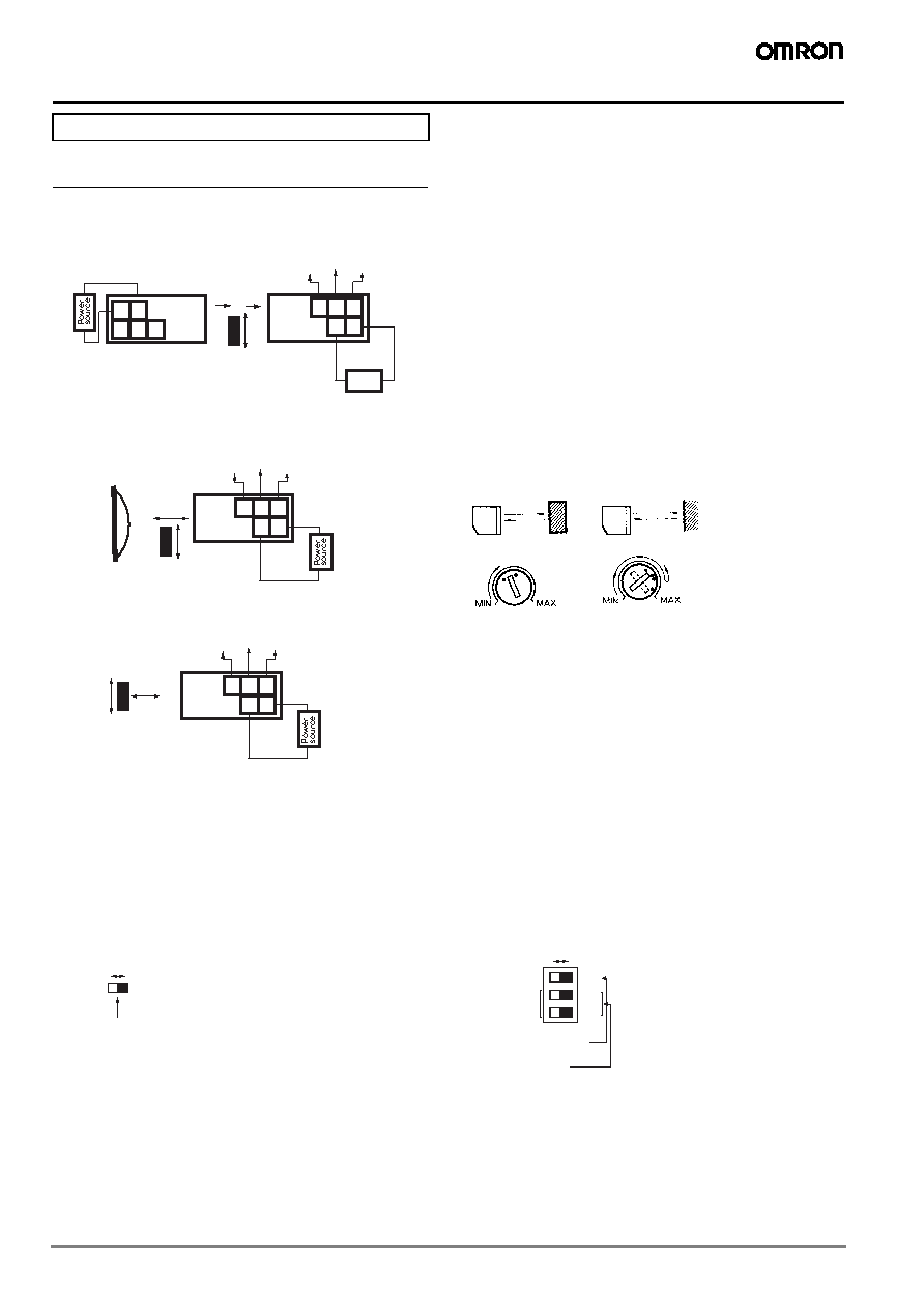 6 Multi voltage photoelectric sensor Precautions Connections Through-beam Models Retro-reflective Models Diffuse-reflective Models Adjustment Through-beam Models For a E3JM with the timer function, the indicator will be lit when incident light is received while the mode is switched to Light-ON, and the indicator will be lit when light is interrupted while the mode is switched to Dark-ON. Move the Emitter and Receiver horizontally and vertically, and locate them to the center of the range in which the Receiver indi- cator is lit. Retro-reflective Models The indicator of the Retro-reflective Model with the timer function is lit in the same way as for the Through-beam Model. As with the Through-beam Model, adjust the Reflector and Sen- sor. Since the directional angle of the E3JM Retro-reflective Model is 1 to 5 degrees, pay careful attention when adjusting the Sensor. Diffuse-reflective Models The indicator of the Diffuse-reflective Model with the timer func- tion is lit in the same way as for the Through-beam Model. 1. If a sensing object is present as shown above, turn the sensi- tivity adjuster clockwise to increase the sensitivity. Point (A) is where the indicator is lit. 2. Remove the sensing object and turn the adjuster clockwise. Point (B) is where the indicator is lit by background objects. 3. Turn the adjuster counterclockwise to decrease the sensitivity, starting from the point (B). Point (C) is where the indicator is lit. 4. The center point between the point (A) and point (C) is the optimum position. If the indicator is not lit by the background object at the maximum sensitivity, set to the center point between the point (A) and the maximum sensitivity. Note: The sensitivity adjuster may be damaged if an excessive force is applied. Precautions for Correct Use Switch Configuration ! Warning This product is not designed or rated for ensuring safety of persons. Do not use it for such purposes. 3 4 5 12 NO Tb COM Tc NC Ta 12 to 240 VDC 24 to 240 VAC Receiver Sensing object Power source 3 4 5 1 2 12 to 240 VDC 24 to 240 VAC Emitter 3 4 5 12 NO Tb COM Tc NC Ta 12 to 240 VDC 24 to 240 VAC Receiver Sensing object E39-R1 Reflector 3 4 5 12 NO Tb COM Tc NC Ta 12 to 240 VDC 24 to 240 VAC Receiver Sensing object Sensing object is present. Sensing object is not present. (A) Operation (C) Release (B) Operation Sensitivity Sensitivity Models without Timer Models with Timer MODE 0 1 D·ON L·ON Switch for operating mode MODE 0 1 D·ON L·ON SW1 SW2 TIMER Switch for operating mode Switch for timer mode |
|
|
Link URL |
| Does ALLDATASHEET help your business so far? [ DONATE ] |
About Alldatasheet | Advertisement | Contact us | Privacy Policy | Link to Datasheet | Link Exchange | Manufacturer List All Rights Reserved©Alldatasheet.com |
| Russian : Alldatasheetru.com | Korean : Alldatasheet.co.kr | Spanish : Alldatasheet.es | French : Alldatasheet.fr | Italian : Alldatasheetit.com Portuguese : Alldatasheetpt.com | Polish : Alldatasheet.pl | Vietnamese : Alldatasheet.vn Indian : Alldatasheet.in | Mexican : Alldatasheet.com.mx | British : Alldatasheet.co.uk | New Zealand : Alldatasheet.co.nz |
|
Family Site : ic2ic.com |
icmetro.com |
 British ▼
 English
 Chinese
 German
 Japanese
 Russian
 Korean
 Spanish
 French
 Italian
 Portuguese
 Polish
 Vietnamese
 Indian
 Mexican
 British
 New Zealand