|
Electronic Components Datasheet Search |
|
|
Electronic Components Datasheet Search |
|
BU52012HFV Datasheet(PDF) 8 Page - Rohm |
|
|
|||||||||||||||||||||||||||||
BU52012HFV Datasheet(HTML) 8 Page - Rohm |
|
|
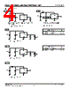
8 / 14 page  Technical Note BU52002GUL,BU52003GUL,BU52012HFV,BU52013HFV 8/13 www.rohm.com 2010.01 - Rev.B © 2010 ROHM Co., Ltd. All rights reserved. ● Description of Operations (Micropower Operation) (Offset Cancelation) (Magnetic Field Detection Mechanism) The Hall IC cannot detect magnetic fields that run horizontal to the package top layer. Be certain to configure the Hall IC so that the magnetic field is perpendicular to the top layer. The unipolar detection Hall IC adopts an intermittent operation method to save energy. At startup, the Hall elements, amp, comparator and other detection circuits power ON and magnetic detection begins. During standby, the detection circuits power OFF, thereby reducing current consumption. The detection results are held while standby is active, and then output. Reference period: 50ms (MAX100ms) Reference startup time: 24μs IDD Standby Startup time Period t Fig.32 The Hall elements form an equivalent Wheatstone (resistor) bridge circuit. Offset voltage may be generated by a differential in this bridge resistance, or can arise from changes in resistance due to package or bonding stress. A dynamic offset cancellation circuit is employed to cancel this offset voltage. When Hall elements are connected as shown in Fig. 33 and a magnetic field is applied perpendicular to the Hall elements, voltage is generated at the mid-point terminal of the bridge. This is known as Hall voltage. Dynamic cancellation switches the wiring (shown in the figure) to redirect the current flow to a 90˚ angle from its original path, and thereby cancels the Hall voltage. The magnetic signal (only) is maintained in the sample/hold circuit during the offset cancellation process and then released. + GND VDD - I B × Hall Voltage Fig.33 Fig.34 S S N S N S N Flux Flux |
|
|
Link URL |
| Does ALLDATASHEET help your business so far? [ DONATE ] |
About Alldatasheet | Advertisement | Contact us | Privacy Policy | Link to Datasheet | Link Exchange | Manufacturer List All Rights Reserved©Alldatasheet.com |
| Russian : Alldatasheetru.com | Korean : Alldatasheet.co.kr | Spanish : Alldatasheet.es | French : Alldatasheet.fr | Italian : Alldatasheetit.com Portuguese : Alldatasheetpt.com | Polish : Alldatasheet.pl | Vietnamese : Alldatasheet.vn Indian : Alldatasheet.in | Mexican : Alldatasheet.com.mx | British : Alldatasheet.co.uk | New Zealand : Alldatasheet.co.nz |
|
Family Site : ic2ic.com |
icmetro.com |
 British ▼
 English
 Chinese
 German
 Japanese
 Russian
 Korean
 Spanish
 French
 Italian
 Portuguese
 Polish
 Vietnamese
 Indian
 Mexican
 British
 New Zealand