|
Electronic Components Datasheet Search |
|
|
Electronic Components Datasheet Search |
|
OP4004B Datasheet(PDF) 4 Page - Murata Manufacturing Co., Ltd. |
|
|
|||||||||||||||||||||||||||||
OP4004B Datasheet(HTML) 4 Page - Murata Manufacturing Co., Ltd. |
|
|
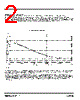
4 / 7 page  www.RFM.com E-mail: info@rfm.com Page 4 of 7 ©2008 by RF Monolithics, Inc. OP4004B - 3/27/08 Output DC Voltage Configurability - the OP4004B differential outputs can be DC-configured to support a wide range of high-speed logic families and ASIC drive requirements by the selection of four resistors (see Configuring the OP4004B DC Output Voltage below) and a logic supply voltage. Each differential output of the OP4004B is AC-coupled to provide this flexibility. OP4004B Tuning Details The frequency tuning of the OP4004B is characterized over a voltage range of 0 to 3.3 V. The tuning voltage applied to the OP4004B should be limited to this range. Figure 4 shows the typical locked tuning range for operation over -40 or +85 °C. The frequency shift of a quartz SAW frequency control device with temperature has the shape of an inverted parabola, with the highest frequency occurring around +25 °C. At both -40 and +85 °C, there will be a 170 ppm downward shift in the frequency of the SAW device compared to +25 °C. Tuning to compensate for this temperature shift is the same as tuning 170 ppm higher at +25 °C. This is well within the tuning range of the OP4004B, as shown in Figure 4. Note that the voltage tuning constant, KV, is bounded between 140 and 300 ppm/V under locked conditions for any temperature within the OP4004B's specified operating range. Differential Output Symmetry - for balanced output loads, the differential output symmetry of the OP4004B is ±1%. This differential output symmetry meets the requirements of the most demanding high-speed logic families. The OP4004B tuning port presents a input impedance greater than 100 kilohms from DC to 50 kHz, and at least 1 kilohm for any RF frequency up to the operating frequency of the OP4004B. Most operational amplifiers used in active loop filters will be stable when driving the tuning port directly. Special care are should be taken to avoid ground loops in the path from the output of the phase detector though the loop filter to the tuning input of the OP4004B. For most applications, the bandwidth of the loop filter in a OP4004B PLL will be less than 50 Hz, as discussed in the example OP4004B PLL application section below. Configuring the OP4004B DC Output Voltage Each differential output of the OP4004B is AC coupled, allowing the static DC level at each output to be set with a resistive divider to match the logic family being driven by the clock. The parallel-equivalent resistance of the two resistors in each divider should be approximately 50 ohms. The supply voltage to the dividers, VLOAD, should be two to three times the value of the static DC voltage, VDC. Referring to the accompanying figure : VDC = VLOAD*R1/(R1 + R2) and 50 = R1*R2/(R1 + R2) The values of the resistors R2 and R1 are given directly as: R2 = 50*VLOAD/VDC R1 = 1/(0.02 - (1/R2)) R1 R1 R2 R2 3.3 Vdc V Load OP4004B TUNE V DC V DC V LOAD OP4004B DC Output Voltage Adjustment |
|
|
Link URL |
| Does ALLDATASHEET help your business so far? [ DONATE ] |
About Alldatasheet | Advertisement | Contact us | Privacy Policy | Link to Datasheet | Link Exchange | Manufacturer List All Rights Reserved©Alldatasheet.com |
| Russian : Alldatasheetru.com | Korean : Alldatasheet.co.kr | Spanish : Alldatasheet.es | French : Alldatasheet.fr | Italian : Alldatasheetit.com Portuguese : Alldatasheetpt.com | Polish : Alldatasheet.pl | Vietnamese : Alldatasheet.vn Indian : Alldatasheet.in | Mexican : Alldatasheet.com.mx | British : Alldatasheet.co.uk | New Zealand : Alldatasheet.co.nz |
|
Family Site : ic2ic.com |
icmetro.com |
 British ▼
 English
 Chinese
 German
 Japanese
 Russian
 Korean
 Spanish
 French
 Italian
 Portuguese
 Polish
 Vietnamese
 Indian
 Mexican
 British
 New Zealand