|
Electronic Components Datasheet Search |
|
|
Electronic Components Datasheet Search |
|
ADP5070AREZ-R7 Datasheet(PDF) 20 Page - Analog Devices |
|
|
|||||||||||||||||||||||||||||
ADP5070AREZ-R7 Datasheet(HTML) 20 Page - Analog Devices |
|
|
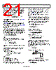
20 / 28 page  Data Sheet ADP5070 Rev. A | Page 19 of 27 For the inductor ripple current in continuous conduction mode (CCM) operation, the input (VIN) and output (VPOS) voltages determine the switch duty cycle (DUTY1) by + + − = DIODE1 POS DIODE1 IN POS 1 V V V V V DUTY where VDIODE1 is the forward voltage drop of the Schottky diode (D1). The dc input current in CCM (IIN) can be determined by the following equation: ) 1 ( 1 OUT1 IN DUTY I I − = Using the duty cycle (DUTY1) and switching frequency (fSW), determine the on time (tON1) using the following equation: SW 1 ON1 f DUTY t = The inductor ripple current (∆IL1) in steady state is calculated by L1 t V I ON1 IN L1 × = ∆ Solve for the inductance value (L1) using the following equation: L1 ON1 IN I t V L1 ∆ × = Assuming an inductor ripple current of 30% of the maximum dc input current results in OUT1 1 ON1 IN I DUTY t V L1 × − × × = 3 . 0 ) 1 ( Ensure that the peak inductor current (the maximum input current plus half the inductor ripple current) is below the rated saturation current of the inductor. Likewise, ensure that the maximum rated rms current of the inductor is greater than the maximum dc input current to the regulator. When the ADP5070 boost regulator is operated in CCM at duty cycles greater than 50%, slope compensation is required to stabilize the current mode loop. This slope compensation is built in to the ADP5070. For stable current mode operation, ensure that the selected inductance is equal to or greater than the minimum calculated inductance, LMIN1, for the application parameters in the following equation: − − × = > 33 . 0 ) 1 ( 27 . 0 1 IN MIN1 DUTY V L L1 (µH) Table 10 suggests a series of inductors to use with the ADP5070 boost regulator. Inductor Selection for the Inverting Regulator The inductor stores energy during the on time of the power switch, and transfers that energy to the output through the output rectifier during the off time. To balance the tradeoffs between small inductor current ripple and efficiency, inductance values in the range of 1 µH to 22 µH are recommended. In general, lower inductance values have higher saturation current and lower series resistance for a given physical size. However, lower inductance results in a higher peak current that can lead to reduced efficiency and greater input and/or output ripple and noise. A peak-to-peak inductor ripple current close to 30% of the maximum dc current in the inductor typically yields an optimal compromise. For the inductor ripple current in continuous conduction mode (CCM) operation, the input (VIN) and output (VNEG) voltages determine the switch duty cycle (DUTY2) by + + + = DIODE2 NEG IN DIODE2 NEG 2 V V V V V DUTY | | | | where VDIODE2 is the forward voltage drop of the Schottky diode (D2). The dc current in the inductor in CCM (IL2) can be determined by the following equation: ) 1 ( 2 OUT2 L2 DUTY I I − = Using the duty cycle (DUTY2) and switching frequency (fSW), determine the on time (tON2) by the following equation: SW 2 ON2 f DUTY t = The inductor ripple current (∆IL2) in steady state is calculated by L2 t V I ON2 IN L2 × = ∆ Solve for the inductance value (L2) by the following equation: L2 ON2 IN I t V L2 ∆ × = Assuming an inductor ripple current of 30% of the maximum dc current in the inductor results in OUT2 2 ON2 IN I DUTY t V L2 × − × × = 3 . 0 ) 1 ( Ensure that the peak inductor current (the maximum input current plus half the inductor ripple current) is below the rated saturation current of the inductor. Likewise, ensure that the maximum rated rms current of the inductor is greater than the maximum dc input current to the regulator. |
|
Link URL |
| Does ALLDATASHEET help your business so far? [ DONATE ] |
About Alldatasheet | Advertisement | Contact us | Privacy Policy | Link to Datasheet | Link Exchange | Manufacturer List All Rights Reserved©Alldatasheet.com |
| Russian : Alldatasheetru.com | Korean : Alldatasheet.co.kr | Spanish : Alldatasheet.es | French : Alldatasheet.fr | Italian : Alldatasheetit.com Portuguese : Alldatasheetpt.com | Polish : Alldatasheet.pl | Vietnamese : Alldatasheet.vn Indian : Alldatasheet.in | Mexican : Alldatasheet.com.mx | British : Alldatasheet.co.uk | New Zealand : Alldatasheet.co.nz |
|
Family Site : ic2ic.com |
icmetro.com |
 British ▼
 English
 Chinese
 German
 Japanese
 Russian
 Korean
 Spanish
 French
 Italian
 Portuguese
 Polish
 Vietnamese
 Indian
 Mexican
 British
 New Zealand