|
Electronic Components Datasheet Search |
|
|
Electronic Components Datasheet Search |
|
XR81112 Datasheet(PDF) 9 Page - Exar Corporation |
|
|
|||||||||||||||||||||||||||||
XR81112 Datasheet(HTML) 9 Page - Exar Corporation |
|
|
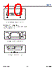
9 / 12 page  © 2014 Exar Corporation XR81112 9 / 12 exar.com/XR81112 Rev 1A Application Information Functional Truth Table The XR81112 Universal Clock can support up to 4 individual output frequency configurations. Once configured, the two frequency select pins, FSLEL[1:0], will determine the output frequency from the device. This allows the XR81112 to sup- port a variety of applications. If the FSEL pins are left float- ing, the XR81112 will default (with internal pull-down resistors on the FSEL inputs) to the Frequency #1 output. Termination for LVPECL Outputs The termination schemes shown in Figure 5 and Figure 6 are typical for LVPECL outputs. Matched impedance layout techniques should be used for the LVPECL output pairs to minimize any distortion that could impact your maximum operating frequency. Figure 7 is an alternate termination scheme that uses a Y-termination approach. Figure 5: XR81112 3.3V LVPECL Output Termination Figure 6: XR81112 2.5V LVPECL Output Termination Figure 7: XR81112 Alternate LVPECL Output Termination Using Y-termination Termination for LVDS Outputs The termination schemes shown in Figure 8 and Figure 9 are typical for LVDS outputs. LVDS swing is a small , typi- cally 350mV, on 1.2V of common mode. The LVDS output pair needs a 100 resistor across the differential pair as close to the destination as possible. Figure 8: XR81112 3.3V LVDS Output Termination Table 1: Output Frequency Selection FSEL[1:0] Output Frequency (MHz) 00 Frequency #1 01 Frequency #2 10 Frequency #3 11 Frequency #4 3.3V 3.3V 3.3V 50 50 130 130 82 82 LVPECL Output LVPECL Input 2.5V 2.5V 2.5V 50 50 LVPECL Output LVPECL Input VCC VCC 50 50 50 50 LVPECL Output LVPECL Input RTT For 3.3V systems RTT= 50 For 2.5V systems RTT= 19 3.3V 3.3V 50 50 100 LVDS Output LVDS Input |
|
|
Link URL |
| Does ALLDATASHEET help your business so far? [ DONATE ] |
About Alldatasheet | Advertisement | Contact us | Privacy Policy | Link to Datasheet | Link Exchange | Manufacturer List All Rights Reserved©Alldatasheet.com |
| Russian : Alldatasheetru.com | Korean : Alldatasheet.co.kr | Spanish : Alldatasheet.es | French : Alldatasheet.fr | Italian : Alldatasheetit.com Portuguese : Alldatasheetpt.com | Polish : Alldatasheet.pl | Vietnamese : Alldatasheet.vn Indian : Alldatasheet.in | Mexican : Alldatasheet.com.mx | British : Alldatasheet.co.uk | New Zealand : Alldatasheet.co.nz |
|
Family Site : ic2ic.com |
icmetro.com |
 British ▼
 English
 Chinese
 German
 Japanese
 Russian
 Korean
 Spanish
 French
 Italian
 Portuguese
 Polish
 Vietnamese
 Indian
 Mexican
 British
 New Zealand