|
Electronic Components Datasheet Search |
|
|
Electronic Components Datasheet Search |
|
DS28E17 Datasheet(PDF) 8 Page - Maxim Integrated Products |
|
|
|||||||||||||||||||||||||||||
DS28E17 Datasheet(HTML) 8 Page - Maxim Integrated Products |
|
|
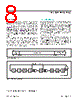
8 / 27 page  64-Bit ROM ID Each DS28E17 contains a unique ROM ID that is 64 bits long. The first 8 bits are a 1-Wire family code. The next 48 bits are a unique serial number. The last 8 bits are a cyclic redundancy check (CRC) of the first 56 bits. See Figure 2 for details. The 1-Wire CRC is generated using a polynomial generator consisting of a shift register and XOR gates as shown in Figure 3. The polynomial is X8 + X5 + X4 + 1. Additional information about the 1-Wire CRC is available in Application Note 27: Understanding and Using Cyclic Redundancy Checks with Maxim iButton® Products. The shift register bits are initialized to 0. Then, starting with the least significant bit of the family code, one bit at a time is shifted in. After the 8th bit of the family code has been entered, the serial number is entered. After the last bit of the serial number has been entered, the shift reg- ister contains the CRC value. Shifting in the 8 bits of the CRC returns the shift register to all 0s. 1-Wire Bus System The 1-Wire bus is a system that has a single bus master and one or more slaves. In all instances the DS28E17 is a slave device. The bus master is typically a microcon- troller. The discussion of this bus system is broken down into three topics: hardware configuration, transaction sequence, and 1-Wire signaling (signal types and timing). The 1-Wire protocol defines bus transactions in terms of the bus state during specific time slots, which are initiated on the falling edge of sync pulses from the bus master. Hardware Configuration The 1-Wire bus has only a single line by definition; it is important that each device on the bus be able to drive it at the appropriate time. To facilitate this, each device attached to the 1-Wire bus must have open-drain or three-state outputs. The 1-Wire port (i.e., IO pin) of the DS28E17 is open drain or an input to read data. iButton is a registered trademark of Maxim Integrated Products, Inc. Figure 2. 64-Bit ROM ID Figure 3. 1-Wire CRC Generator DS28E17 1-Wire-to-I2C Master Bridge www.maximintegrated.com Maxim Integrated │ 8 MSb 8-BIT CRC CODE 48-BIT SERIAL NUMBER MSb LSb MSb LSb LSb 8-BIT FAMILY CODE (19h) MSb LSb 1ST STAGE 2ND STAGE 3RD STAGE 4TH STAGE 7TH STAGE 8TH STAGE 6TH STAGE 5TH STAGE X0 X1 X2 X3 X4 POLYNOMIAL = X8 + X5 + X4 + 1 INPUT DATA X5 X6 X7 X8 |
|
Link URL |
| Does ALLDATASHEET help your business so far? [ DONATE ] |
About Alldatasheet | Advertisement | Contact us | Privacy Policy | Link to Datasheet | Link Exchange | Manufacturer List All Rights Reserved©Alldatasheet.com |
| Russian : Alldatasheetru.com | Korean : Alldatasheet.co.kr | Spanish : Alldatasheet.es | French : Alldatasheet.fr | Italian : Alldatasheetit.com Portuguese : Alldatasheetpt.com | Polish : Alldatasheet.pl | Vietnamese : Alldatasheet.vn Indian : Alldatasheet.in | Mexican : Alldatasheet.com.mx | British : Alldatasheet.co.uk | New Zealand : Alldatasheet.co.nz |
|
Family Site : ic2ic.com |
icmetro.com |
 British ▼
 English
 Chinese
 German
 Japanese
 Russian
 Korean
 Spanish
 French
 Italian
 Portuguese
 Polish
 Vietnamese
 Indian
 Mexican
 British
 New Zealand