|
Electronic Components Datasheet Search |
|
|
Electronic Components Datasheet Search |
|
UU28121G-AF5-R Datasheet(PDF) 4 Page - Unisonic Technologies |
|
|
|||||||||||||||||||||||||||||
UU28121G-AF5-R Datasheet(HTML) 4 Page - Unisonic Technologies |
|
|
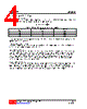
4 / 6 page 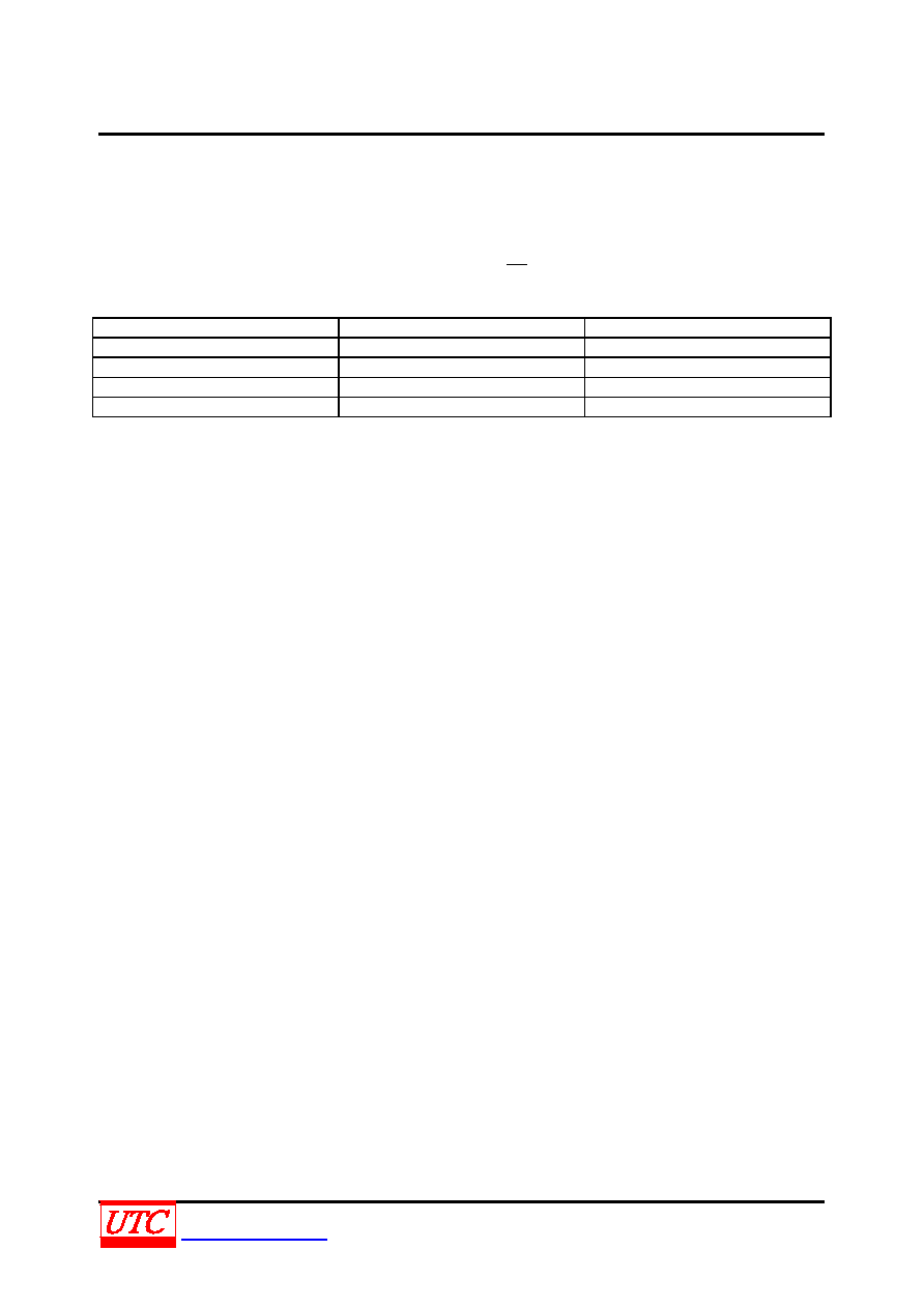 UU28121 CMOS IC UNISONICTECHNOLOGIESCO.,LTD 4 of 6 www.unisonic.com.tw QW-R135-001.C FUNCTION DESCRIPTION Setting the Output Voltage Application circuit item shows the basic application circuit with UTC UU28121 adjustable output version. The external resistor sets the output voltage according to the following equation: VOUT=1.238V×(1+ 1 R 2 R ) Table 1. Resistor Selection for Common Output Voltages VOUT(V) R1(kΩ) R2(kΩ) 12 54 470 16 39 470 24 39 720 27 36 750 For most applications, R2 is a suggested a value by 300K~850KΩ. Place the resistor-divider as close to the IC as possible to reduce the noise sensitivity. Under Voltage Lockout (UVLO) To avoid mis-operation of the device at low input voltages an under voltage lockout is included that disables the device, if the input voltage falls below (2.25V~200mV). Input Capacitor Selection The input capacitor reduces the surge current drawn from the input and switching noise from the device. The input capacitor impedance at the switching frequency shall be less than input source impedance to prevent high frequency switching current passing to the input. A low ESR input capacitor sized for maximum RMS current must be used. Ceramic capacitors with X5R or X7R dielectrics are highly recommended because of their low ESR and small temperature coefficients. A 4.7µF ceramic capacitor for most applications is sufficient. For a lower output power requirement application, this value can be decreased. Output Capacitor Selection The output capacitor is required to keep the output voltage ripple small and to ensure regulation loop stability. The output capacitor must have low impedance at the switching frequency. Ceramic capacitors with X5R or X7R dielectrics are recommended due to their low ESR and high ripple current. A 2.2uF ceramic capacitors works for most of the applications. Higher capacitor values can be used to improve the load transient response. |
|
|
Link URL |
| Does ALLDATASHEET help your business so far? [ DONATE ] |
About Alldatasheet | Advertisement | Contact us | Privacy Policy | Link to Datasheet | Link Exchange | Manufacturer List All Rights Reserved©Alldatasheet.com |
| Russian : Alldatasheetru.com | Korean : Alldatasheet.co.kr | Spanish : Alldatasheet.es | French : Alldatasheet.fr | Italian : Alldatasheetit.com Portuguese : Alldatasheetpt.com | Polish : Alldatasheet.pl | Vietnamese : Alldatasheet.vn Indian : Alldatasheet.in | Mexican : Alldatasheet.com.mx | British : Alldatasheet.co.uk | New Zealand : Alldatasheet.co.nz |
|
Family Site : ic2ic.com |
icmetro.com |
 British ▼
 English
 Chinese
 German
 Japanese
 Russian
 Korean
 Spanish
 French
 Italian
 Portuguese
 Polish
 Vietnamese
 Indian
 Mexican
 British
 New Zealand