 |
Electronic Components Datasheet Search |
|
|
Electronic Components Datasheet Search |
|
EM357-RTR Datasheet(PDF) 122 Page - Silicon Laboratories |
|
|
|||||||||||||||||||||||||||||
EM357-RTR Datasheet(HTML) 122 Page - Silicon Laboratories |
|
|
122 / 241 page 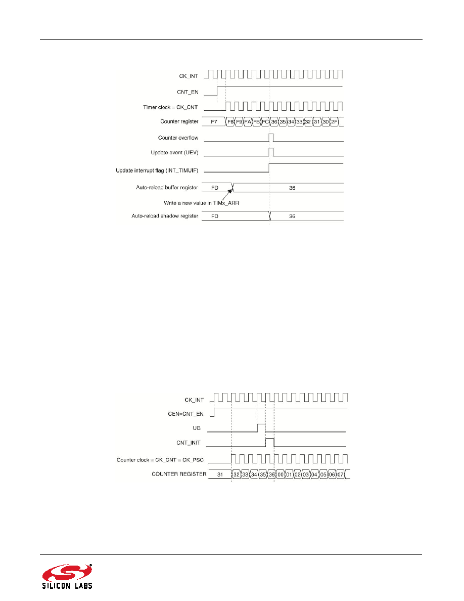 Rev 1.3 122 Figure 9.11. Counter Timing Diagram, Update Event with TIM_ARBE = 1 (Counter Overflow) 9.3.3. Clock Selection The counter clock can be provided by the following clock sources: Internal clock (PCLK) External clock mode 1: external input pin (TIy) External clock mode 2: external trigger input (ETR) Internal trigger input (ITR0): using the other timer as prescaler. Refer to "9.3.14.1. Using One Timer as Prescaler for the Other Timer" on page 139 for more details. 9.3.3.1. Internal Clock Source (CK_INT) The internal clock is selected when the slave mode controller is disabled (TIM_SMS = 000 in the TIMx_SMCR register). In this mode, the TIM_CEN, TIM_DIR (in the TIMx_CR1 register), and TIM_UG bits (in the TIMx_EGR register) are actual control bits and can be changed only by software, except for TIM_UG, which remains cleared automatically. As soon as the TIM_CEN bit is written to 1, the prescaler is clocked by the internal clock CK_INT. Figure 9.12 shows the behavior of the control circuit and the up-counter in normal mode, without prescaling. Figure 9.12. Control Circuit in Normal Mode, Internal Clock Divided by 1 |
|
Link URL |
| Does ALLDATASHEET help your business so far? [ DONATE ] |
About Alldatasheet | Advertisement | Contact us | Privacy Policy | Link to Datasheet | Link Exchange | Manufacturer List All Rights Reserved©Alldatasheet.com |
| Russian : Alldatasheetru.com | Korean : Alldatasheet.co.kr | Spanish : Alldatasheet.es | French : Alldatasheet.fr | Italian : Alldatasheetit.com Portuguese : Alldatasheetpt.com | Polish : Alldatasheet.pl | Vietnamese : Alldatasheet.vn Indian : Alldatasheet.in | Mexican : Alldatasheet.com.mx | British : Alldatasheet.co.uk | New Zealand : Alldatasheet.co.nz |
|
Family Site : ic2ic.com |
icmetro.com |
 British ▼
 English
 Chinese
 German
 Japanese
 Russian
 Korean
 Spanish
 French
 Italian
 Portuguese
 Polish
 Vietnamese
 Indian
 Mexican
 British
 New Zealand


