 |
Electronic Components Datasheet Search |
|
|
Electronic Components Datasheet Search |
|
EM357-RTR Datasheet(PDF) 131 Page - Silicon Laboratories |
|
|
|||||||||||||||||||||||||||||
EM357-RTR Datasheet(HTML) 131 Page - Silicon Laboratories |
|
|
131 / 241 page 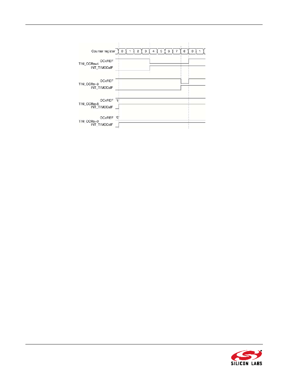 131 Rev 1.3 Figure 9.22. Edge-Aligned PWM Waveforms (ARR = 8) 9.3.9.2. PWM Edge-Aligned Mode: Down-Counting Configuration Down-counting is active when the TIM_DIR bit in the TIMx_CR1 register is high. Refer to "9.3.2.2. Down-Counting Mode" on page 119 for more information. In PWM mode 1, the reference signal OCyREF is low as long as TIMx_CNT > TIMx_CCRy, otherwise it becomes high. If the compare value in TIMx_CCRy is greater than the auto-reload value in TIMx_ARR, then OCyREF is held at 1. Zero-percent PWM is not possible in this mode. 9.3.9.3. PWM Center-Aligned Mode Center-aligned mode is active except when the TIM_CMS bits in the TIMx_CR1 register are 00 (all configurations where TIM_CMS is non-zero have the same effect on the OCyREF/OCy signals). The compare flag is set when the counter counts up, when it counts down, or when it counts up and down, depending on the TIM_CMS bits configuration. The direction bit (TIM_DIR) in the TIMx_CR1 register is updated by hardware and must not be changed by software. Refer to the "9.3.2.3. Center-Aligned Mode (Up/Down Counting)" on page 120 for more information. Figure 9.23 shows some center-aligned PWM waveforms in an example where: TIMx_ARR = 8 PWM mode is the PWM mode 1 The output compare flag is set when the counter counts down corresponding to the center-aligned mode 1 selected for TIM_CMS = 01 in the TIMx_CR1 register |
|
Link URL |
| Does ALLDATASHEET help your business so far? [ DONATE ] |
About Alldatasheet | Advertisement | Contact us | Privacy Policy | Link to Datasheet | Link Exchange | Manufacturer List All Rights Reserved©Alldatasheet.com |
| Russian : Alldatasheetru.com | Korean : Alldatasheet.co.kr | Spanish : Alldatasheet.es | French : Alldatasheet.fr | Italian : Alldatasheetit.com Portuguese : Alldatasheetpt.com | Polish : Alldatasheet.pl | Vietnamese : Alldatasheet.vn Indian : Alldatasheet.in | Mexican : Alldatasheet.com.mx | British : Alldatasheet.co.uk | New Zealand : Alldatasheet.co.nz |
|
Family Site : ic2ic.com |
icmetro.com |
 British ▼
 English
 Chinese
 German
 Japanese
 Russian
 Korean
 Spanish
 French
 Italian
 Portuguese
 Polish
 Vietnamese
 Indian
 Mexican
 British
 New Zealand


