 |
Electronic Components Datasheet Search |
|
|
Electronic Components Datasheet Search |
|
EM357-RTR Datasheet(PDF) 135 Page - Silicon Laboratories |
|
|
|||||||||||||||||||||||||||||
EM357-RTR Datasheet(HTML) 135 Page - Silicon Laboratories |
|
|
135 / 241 page 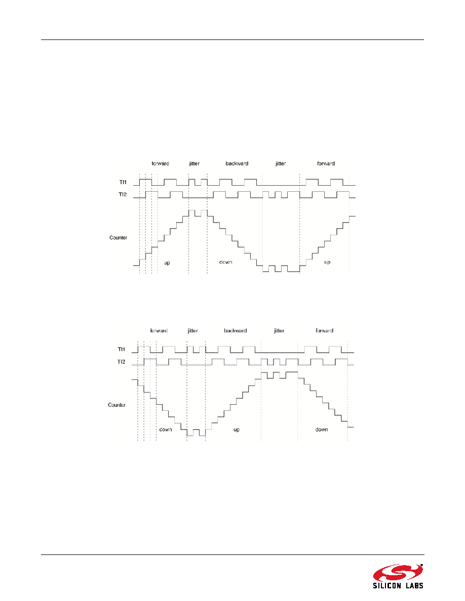 135 Rev 1.3 Figure 9.25 gives an example of counter operation, showing count signal generation and direction control. It also shows how input jitter is compensated for when both inputs are used for counting. This might occur if the sensor is positioned near one of the switching points. This example assumes the following configuration: TIM_CC1S = 01 (TIMx_CCMR1 register, IC1FP1 mapped on TI1). TIM_CC2S = 01 (TIMx_CCMR2 register, IC2FP2 mapped on TI2). TIM_CC1P = 0 (TIMx_CCER register, IC1FP1 non-inverted, IC1FP1 = TI1). TIM_CC2P = 0 (TIMx_CCER register, IC2FP2 non-inverted, IC2FP2 = TI2). TIM_SMS = 011 (TIMx_SMCR register, both inputs are active on both rising and falling edges). TIM_CEN = 1 (TIMx_CR1 register, counter is enabled). Figure 9.25. Example of Counter Operation in Encoder Interface Mode Figure 9.26 gives an example of counter behavior when IC1FP1 polarity is inverted (same configuration as above except TIM_CC1P = 1). Figure 9.26. Example of Encoder Interface Mode with IC1FP1 Polarity Inverted The timer configured in encoder interface mode provides information on a sensor’s current position. To obtain dynamic information (speed, acceleration/deceleration), measure the period between two encoder events using a second timer configured in capture mode. The output of the encoder that indicates the mechanical zero can be used for this purpose. Depending on the time between two events, the counter can also be read at regular times. Do this by latching the counter value into a third input capture register. (In this case the capture signal must be periodic and can be generated by another timer). |
|
Link URL |
| Does ALLDATASHEET help your business so far? [ DONATE ] |
About Alldatasheet | Advertisement | Contact us | Privacy Policy | Link to Datasheet | Link Exchange | Manufacturer List All Rights Reserved©Alldatasheet.com |
| Russian : Alldatasheetru.com | Korean : Alldatasheet.co.kr | Spanish : Alldatasheet.es | French : Alldatasheet.fr | Italian : Alldatasheetit.com Portuguese : Alldatasheetpt.com | Polish : Alldatasheet.pl | Vietnamese : Alldatasheet.vn Indian : Alldatasheet.in | Mexican : Alldatasheet.com.mx | British : Alldatasheet.co.uk | New Zealand : Alldatasheet.co.nz |
|
Family Site : ic2ic.com |
icmetro.com |
 British ▼
 English
 Chinese
 German
 Japanese
 Russian
 Korean
 Spanish
 French
 Italian
 Portuguese
 Polish
 Vietnamese
 Indian
 Mexican
 British
 New Zealand


