|
Electronic Components Datasheet Search |
|
|
Electronic Components Datasheet Search |
|
AS29LV400 Datasheet(PDF) 7 Page - Alliance Semiconductor Corporation |
|
|
|||||||||||||||||||||||||||||
AS29LV400 Datasheet(HTML) 7 Page - Alliance Semiconductor Corporation |
|
|
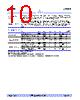
7 / 25 page  ® AS29LV400 March 2001 3/20/01; V.0.9.3 Alliance Semiconductor P. 7 of 25 Command definitions Item Description Reset/Read Initiate read or reset operations by writing the Read/Reset command sequence into the command register. This allows the microprocessor to retrieve data from the memory. Device remains in read mode until command register contents are altered. Device automatically powers up in read/reset state. This feature allows only reads, therefore ensuring no spurious memory content alterations during power up. ID Read AS29LV400 provides manufacturer and device codes in two ways. External PROM programmers typically access the device codes by driving +10V on A9. AS29LV400 also contains an ID Read command to read the device code with only +3V, since multiplexing +10V on address lines is generally undesirable. Initiate device ID read by writing the ID Read command sequence into the command register. Follow with a read sequence from address XXX00h to return MFR code. Follow ID Read command sequence with a read sequence from address XXX01h to return device code. To verify write protect status on sectors, read address XXX02h. Sector addresses A17–A12 produce a 1 on DQ0 for protected sector and a 0 for unprotected sector. Exit from ID read mode with Read/Reset command sequence. Hardware Reset Holding R E S E T low for 500 ns resets the device, terminating any operation in progress; data handled in the operation is corrupted. The internal state machine resets 20 µs after R E S E T is driven low. RY/B Y remains low until internal state machine resets. After R E S E T is set high, there is a delay of 50 ns for the device to permit read operations. Byte/word Programming Programming the AS29LV400 is a four bus cycle operation performed on a byte-by-byte or word- by-word basis. Two unlock write cycles precede the Program Setup command and program data write cycle. Upon execution of the program command, no additional CPU controls or timings are necessary. Addresses are latched on the falling edge of C E or W E , whichever is last; data is latched on the rising edge of C E or W E , whichever is first. The AS29LV400’s automated on-chip program algorithm provides adequate internally-generated programming pulses and verifies the programmed cell margin. Check programming status by sampling data on the RY/B Y pin, or either the DATA polling (DQ7) or toggle bit (DQ6) at the program address location. The programming operation is complete if DQ7 returns equivalent data, if DQ6 = no toggle, or if RY/B Y pin = high. The AS29LV400 ignores commands written during programming. A hardware reset occurring during programming may corrupt the data at the programmed location. AS29LV400 allows programming in any sequence, across any sector boundary. Changing data from 0 to 1 requires an erase operation. Attempting to program data 0 to 1 results in either DQ5 = 1 (exceeded programming time limits); reading this data after a read/reset operation returns a 0. When programming time limit is exceeded, DQ5 reads high, and DQ6 continues to toggle. In this state, a Reset command returns the device to read mode. |
|
|
Link URL |
| Does ALLDATASHEET help your business so far? [ DONATE ] |
About Alldatasheet | Advertisement | Contact us | Privacy Policy | Link to Datasheet | Link Exchange | Manufacturer List All Rights Reserved©Alldatasheet.com |
| Russian : Alldatasheetru.com | Korean : Alldatasheet.co.kr | Spanish : Alldatasheet.es | French : Alldatasheet.fr | Italian : Alldatasheetit.com Portuguese : Alldatasheetpt.com | Polish : Alldatasheet.pl | Vietnamese : Alldatasheet.vn Indian : Alldatasheet.in | Mexican : Alldatasheet.com.mx | British : Alldatasheet.co.uk | New Zealand : Alldatasheet.co.nz |
|
Family Site : ic2ic.com |
icmetro.com |
 British ▼
 English
 Chinese
 German
 Japanese
 Russian
 Korean
 Spanish
 French
 Italian
 Portuguese
 Polish
 Vietnamese
 Indian
 Mexican
 British
 New Zealand