 |
Electronic Components Datasheet Search |
|
|
Electronic Components Datasheet Search |
|
CP10.242-R2 Datasheet(PDF) 20 Page - PULS GmbH |
|
|
|||||||||||||||||||||||||||||
CP10.242-R2 Datasheet(HTML) 20 Page - PULS GmbH |
|
|
20 / 31 page 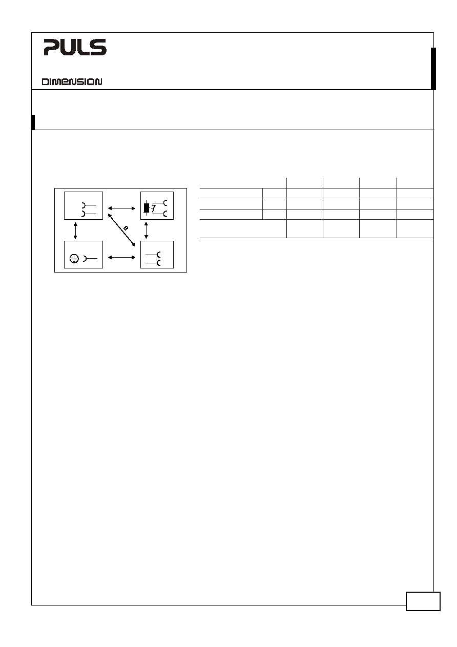 CP10.241-R1, CP10.241-R2, CP10.241-R3,CP10.242-R2 CP-Series 24V, 10A, 240W, SINGLE PHASE Feb. 2018 / CP10.241-R2 Rev0.3-EN - All values are typical figures specified at 230Vac, 50Hz input voltage, 24V, 10A output load, 25°C ambient and after a 5 minutes run-in time unless otherwise noted. www.pulspower.com Phone +49 89 9278 0 Germany 20/31 P R E L I M I N A R Y 19. DIELECTRIC STRENGTH The output voltage is floating and has no ohmic connection to the ground. Type and routine tests are conducted by the manufacturer. Field tests may be conducted in the field using the appropriate test equipment which applies the voltage with a slow ramp (2s up and 2s down). Connect all input-terminals together as well as all output poles before conducting the test. When testing, set the cut-off current settings to the value in the table below. Fig. 19-1 Dielectric strength A B C D Type test 60s 2500Vac 4000Vac 1000Vac 500Vac Routine test 5s 2500Vac 2500Vac 500Vac 500Vac Field test 5s 2000Vac 2000Vac 500Vac 500Vac Cut-off current setting for field test > 10mA > 10mA > 20mA > 1mA AD C B *) N L Input DC-ok Earth, PE Output - + It is recommend that either the + pole, the – pole or any other part of the output circuit shall be connected to the earth/ground system. This helps to avoid situations in which a load starts unexpectedly or can not be switched off when unnoticed earth faults occur. B*) When testing input to DC-OK ensure that the maximal voltage between DC-OK and the output is not exceeded (column D). We recommend connecting DC-OK pins and the output pins together when performing the test. |
|
Link URL |
| Does ALLDATASHEET help your business so far? [ DONATE ] |
About Alldatasheet | Advertisement | Contact us | Privacy Policy | Link to Datasheet | Link Exchange | Manufacturer List All Rights Reserved©Alldatasheet.com |
| Russian : Alldatasheetru.com | Korean : Alldatasheet.co.kr | Spanish : Alldatasheet.es | French : Alldatasheet.fr | Italian : Alldatasheetit.com Portuguese : Alldatasheetpt.com | Polish : Alldatasheet.pl | Vietnamese : Alldatasheet.vn Indian : Alldatasheet.in | Mexican : Alldatasheet.com.mx | British : Alldatasheet.co.uk | New Zealand : Alldatasheet.co.nz |
|
Family Site : ic2ic.com |
icmetro.com |
 British ▼
 English
 Chinese
 German
 Japanese
 Russian
 Korean
 Spanish
 French
 Italian
 Portuguese
 Polish
 Vietnamese
 Indian
 Mexican
 British
 New Zealand


