|
Electronic Components Datasheet Search |
|
|
Electronic Components Datasheet Search |
|
PSAYC-3.3S Datasheet(PDF) 4 Page - Wall Industries,Inc. |
|
|
|||||||||||||||||||||||||||||
PSAYC-3.3S Datasheet(HTML) 4 Page - Wall Industries,Inc. |
|
|
4 / 6 page 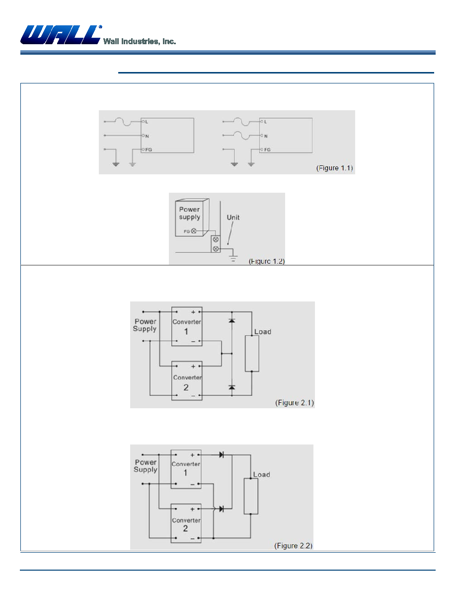 Rev D PSAYC SERIES 2 Watt AC/DC Switching Power Supplies 08/25/2015 Wall Industries, Inc. • 37 Industrial Dr., Exeter, NH 03833 • Tel: 603-778-2300 • Toll Free: 888-597-9255 • Fax 603-778-9797 website: www.wallindustries.com • e-mail: sales@wallindustries.com Page 4 of 6 APPLICATION NOTES AC Input Line Connection: The pin of AC line (L), AC Neutral (N), and the third wire safety ground (FG) should be retained from the AC power outlet to the power supply input terminals without accidental interchange. (Figure 1.1) The FG pin should be connected to the equipment where power supply is placed as thicker and shorter to protect electric shock or noise interference. (Figure 1.2) Series and Parallel Operation I. Series operation: Most power converters can be operated in series if they have overload limitation by either constant current or constant power circuits. To protect each output from the reverse voltage applied by the other unit in the event of load short circuits, reverse biased diodes are used as shown in Figure 2.1. II. Parallel operation: This is only recommended with power converters specifically designed for parallel connection. In the parallel redundant scheme illustrated in Figure 2.2, one of the power converters could be replaced by a battery followed by a DC-DC converter to provide a no-break power sustem in the event of main supply failure. |
|
|
Link URL |
| Does ALLDATASHEET help your business so far? [ DONATE ] |
About Alldatasheet | Advertisement | Contact us | Privacy Policy | Link to Datasheet | Link Exchange | Manufacturer List All Rights Reserved©Alldatasheet.com |
| Russian : Alldatasheetru.com | Korean : Alldatasheet.co.kr | Spanish : Alldatasheet.es | French : Alldatasheet.fr | Italian : Alldatasheetit.com Portuguese : Alldatasheetpt.com | Polish : Alldatasheet.pl | Vietnamese : Alldatasheet.vn Indian : Alldatasheet.in | Mexican : Alldatasheet.com.mx | British : Alldatasheet.co.uk | New Zealand : Alldatasheet.co.nz |
|
Family Site : ic2ic.com |
icmetro.com |
 British ▼
 English
 Chinese
 German
 Japanese
 Russian
 Korean
 Spanish
 French
 Italian
 Portuguese
 Polish
 Vietnamese
 Indian
 Mexican
 British
 New Zealand