|
Electronic Components Datasheet Search |
|
|
Electronic Components Datasheet Search |
|
HTR6545 Datasheet(PDF) 6 Page - Hitachi Semiconductor |
|
|
|||||||||||||||||||||||||||||
HTR6545 Datasheet(HTML) 6 Page - Hitachi Semiconductor |
|
|
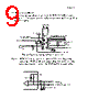
6 / 10 page  Page 5 of 9 7. PINOUT Pinout is shown in Table 4. The mounting studs are for mechanical attachment to the circuit board and are not connected to internal circuit. Table 4. Pin Designations Name Symbol Pin Pin Symbol Name Received Power Monitor (PD bias / APD monitor) RMON 1 20 PMON+ LD Power Monitor(positive) Receiver Ground RGND 2 19 PMON- LD Power Monitor(Negative) Receiver Ground RGND 3 18 BMON+ LD Bias Monitor(positive) No Internal Connection NC 4 17 BMON- LD Bias Monitor(Negative) No Internal Connection NC 5 16 TGND Transmitter Ground Receiver Ground RGND 6 15 DI Transmit DATA(CML) Receiver VCC(+3.3V) RVCC 7 14 DI Transmit DATA(CML) Signal Detect(TTL) SD 8 13 TD Transmitter Disable(TTL) Received DATA(CML) DO 9 12 TGND Transmitter Ground Received DATA(CML) DO 10 11 TVCC Transmitter VCC(+3.3V) Pin 17 to Pin20 are outputs of laser monitoring function. These pins should be connected to high impedance voltage sensing circuit. Internal circuit is shown in Figure 2. If these function are not used, the pins should be open. Figure 2. Equivalent internal circuit of PMON,BMON Vcc Monitor PD laser BMON+ BMON- PMON+ PMON- bias current 3k 3k 3k 3k 200 10 Laser Driver |
|
|
Link URL |
| Does ALLDATASHEET help your business so far? [ DONATE ] |
About Alldatasheet | Advertisement | Contact us | Privacy Policy | Link to Datasheet | Link Exchange | Manufacturer List All Rights Reserved©Alldatasheet.com |
| Russian : Alldatasheetru.com | Korean : Alldatasheet.co.kr | Spanish : Alldatasheet.es | French : Alldatasheet.fr | Italian : Alldatasheetit.com Portuguese : Alldatasheetpt.com | Polish : Alldatasheet.pl | Vietnamese : Alldatasheet.vn Indian : Alldatasheet.in | Mexican : Alldatasheet.com.mx | British : Alldatasheet.co.uk | New Zealand : Alldatasheet.co.nz |
|
Family Site : ic2ic.com |
icmetro.com |
 British ▼
 English
 Chinese
 German
 Japanese
 Russian
 Korean
 Spanish
 French
 Italian
 Portuguese
 Polish
 Vietnamese
 Indian
 Mexican
 British
 New Zealand