|
Electronic Components Datasheet Search |
|
|
Electronic Components Datasheet Search |
|
SC2453 Datasheet(PDF) 13 Page - Semtech Corporation |
|
|
|||||||||||||||||||||||||||||
SC2453 Datasheet(HTML) 13 Page - Semtech Corporation |
|
|
13 / 22 page 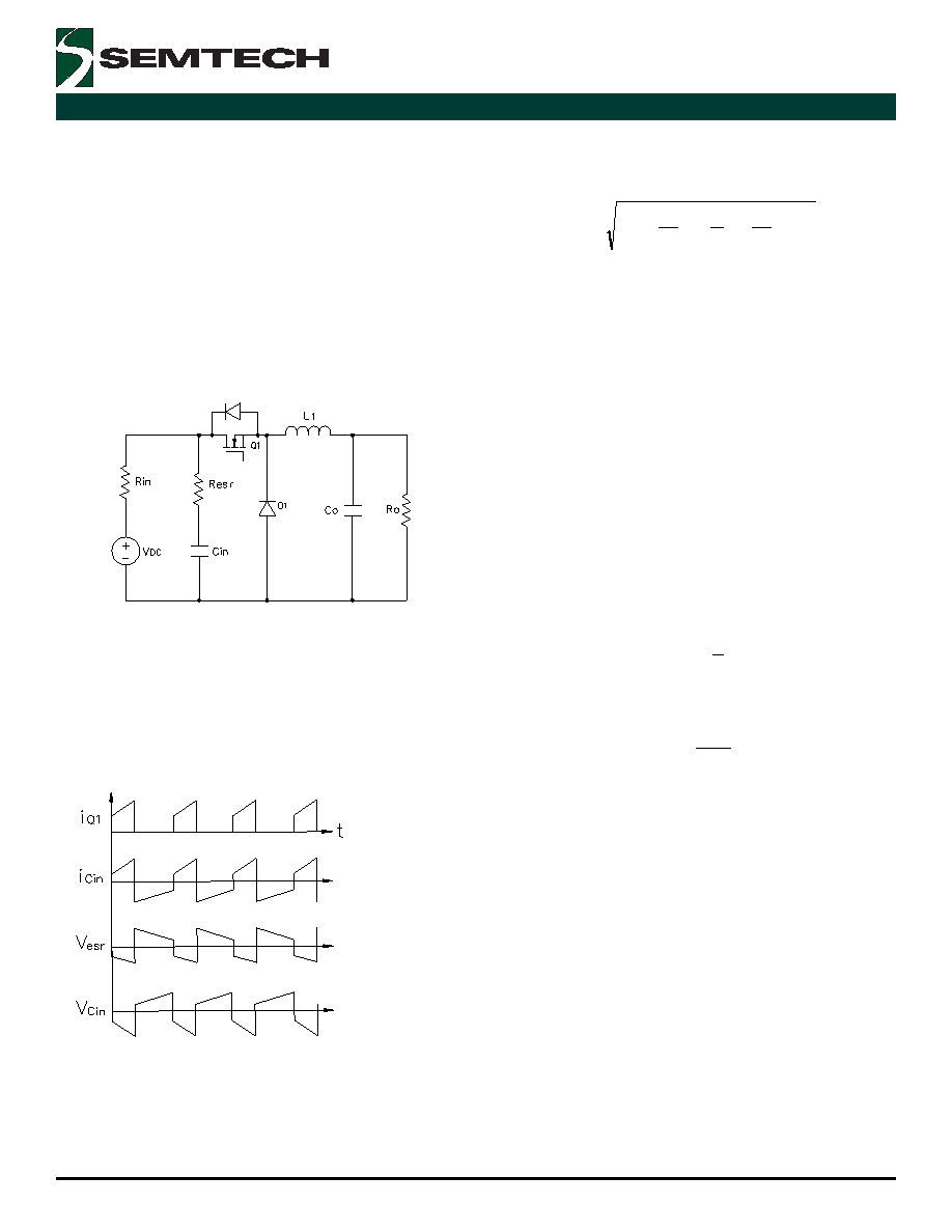 13 2005 Semtech Corp. www.semtech.com SC2453 POWER MANAGEMENT = R 1 and C1a = C1b = C1, then Req and Ceq will be frequency- independent and R eq = 1/2 R1 and Ceq = 2C1 Input Capacitor (C Input Capacitor (C Input Capacitor (C Input Capacitor (C Input Capacitor (C in in in in in))))) The input supply to the converter usually comes from a pre-regulator. Since the input supply is not ideal, input capacitors are needed to filter the current pulses at the switching frequency. A simple buck converter is shown in Figure 3. Figure 3. A simple model for the converter input In Figure 3 the DC input voltage source has an internal impedance R in and the input capacitor Cin has an ESR of R esr. MOSFET and input capacitor current waveforms, ESR voltage ripple and input voltage ripple are shown in Figure 4. Figure 4. Typical waveforms at converter input. It can be seen that the current in the input capacitor pulses with high di/dt. Capacitors with low ESL should be used. It is also important to place the input capacitor close to the MOSFET’s on the PC board to reduce trace inductances around the pulse current loop. The RMS value of the capacitor current is approximately ] ) D 1 ( D ) D 1 )( 12 1 [( D I I 2 2 2 o Cin − η + η − δ + = The power dissipated in the input capacitors is then: P Cin = ICin 2 R esr For reliable operation, the maximum power dissipation in the capacitors should not result in more than 10oC of temperature rise. Many manufacturers specify the maximum allowable ripple current (ARMS) rating of the capacitor at a given ripple frequency and ambient temperature. The input capacitance should be high enough to handle the ripple current. For higher power applications, multiple capacitors are placed in parallel to increase the ripple current handling capability. Sometimes meeting tight input voltage ripple specifications may require the use of larger input capacitance. At full load, the peak-to-peak input voltage ripple due to the ESR is: o esr ESR I) 2 1 ( R v δ + = ∆ The peak-to-peak input voltage ripple due to the capacitor is: s in o C f C DI v ≈ ∆ From these two expressions, C IN can be found to meet the input voltage ripple specification. In a multi-phase converter, channel interleaving can be used to reduce ripple. The two step-down channels of the SC2453 operate at 180 degrees from each other. If both step- down channels in the SC2453 are connected in parallel, both the input and the output RMS currents will be reduced. Ripple cancellation effect of interleaving allows the use of smaller input capacitors. When converter outputs are connected in parallel and interleaved, smaller inductors and capacitors can be used for each channel. The total output ripple-voltage remains unchanged. Smaller inductors speeds up output load transient. When two channels with a common input are interleaved, the total DC input current is simply the sum of the individual DC input currents. The combined input current waveform depends on duty ratio and the output current |
|
|
Link URL |
| Does ALLDATASHEET help your business so far? [ DONATE ] |
About Alldatasheet | Advertisement | Contact us | Privacy Policy | Link to Datasheet | Link Exchange | Manufacturer List All Rights Reserved©Alldatasheet.com |
| Russian : Alldatasheetru.com | Korean : Alldatasheet.co.kr | Spanish : Alldatasheet.es | French : Alldatasheet.fr | Italian : Alldatasheetit.com Portuguese : Alldatasheetpt.com | Polish : Alldatasheet.pl | Vietnamese : Alldatasheet.vn Indian : Alldatasheet.in | Mexican : Alldatasheet.com.mx | British : Alldatasheet.co.uk | New Zealand : Alldatasheet.co.nz |
|
Family Site : ic2ic.com |
icmetro.com |
 British ▼
 English
 Chinese
 German
 Japanese
 Russian
 Korean
 Spanish
 French
 Italian
 Portuguese
 Polish
 Vietnamese
 Indian
 Mexican
 British
 New Zealand