|
Electronic Components Datasheet Search |
|
|
Electronic Components Datasheet Search |
|
CY28330 Datasheet(PDF) 3 Page - SpectraLinear Inc |
|
|
|||||||||||||||||||||||||||||
CY28330 Datasheet(HTML) 3 Page - SpectraLinear Inc |
|
|
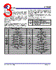
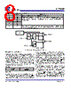
3 / 14 page  CY28330 Rev 1.0, November 21, 2006 Page 3 of 14 Serial Data Interface To enhance the flexibility and function of the clock synthesizer, a two-signal serial interface is provided. Through the Serial Data Interface, various device functions such as individual clock output buffers, etc., can be individually enabled or disabled. The registers associated with the Serial Data Interface initializes to their default setting upon power-up, and therefore use of this interface is optional. Clock device register changes are normally made upon system initialization, if any are required. The interface can also be used during system operation for power management functions. Data Protocol The clock driver serial protocol accepts byte write, byte read, block write, and block read operation from the controller. For block write/read operation, the bytes must be accessed in sequential order from lowest to highest byte (most significant bit first) with the ability to stop after any complete byte has been transferred. For byte write and byte read operations, the system controller can access individual indexed bytes. The offset of the indexed byte is encoded in the command code, as described in Table 2. The block write and block read protocol is outlined in Table 3 while Table 4 outlines the corresponding byte write and byte read protocol. The slave receiver address is 11010010 (D2h). Table 2. Command Code Definition Bit Description 7 0 = Block read or block write operation 1 = Byte read or byte write operation (6:0) Byte offset for byte read or byte write operation. For block read or block write operations, these bits should be '0000000' Table 3. Block Read and Block Write protocol Block Write Protocol Block Read Protocol Bit Description Bit Description 1Start 1 Start 2:8 Slave address - 7 bits 2:8 Slave address - 7 bits 9 Write = 0 9 Write = 0 10 Acknowledge from slave 10 Acknowledge from slave 11:18 Command Code - 8 Bit '00000000' stands for block operation 11:18 Command Code - 8 Bit '00000000' stands for block operation 19 Acknowledge from slave 19 Acknowledge from slave 20:27 Byte Count from master - 8 bits 20 Repeat start 28 Acknowledge from slave 21:27 Slave address - 7 bits 29:36 Data byte 0 from master- 8 bits 28 Read = 1 37 Acknowledge from slave 29 Acknowledge from slave 38:45 Data byte 1 from master - 8 bits 30:37 Byte count from slave - 8 bits 46 Acknowledge from slave 38 Acknowledge .... Data bytes from master/Acknowledge 39:46 Data byte 0 from slave - 8 bits .... Data Byte N - 8 bits 47 Acknowledge .... Acknowledge from slave 48:55 Data byte 1 from slave - 8 bits .... Stop 56 Acknowledge .... Data bytes from slave/Acknowledge .... Data byte N from slave - 8 bits .... Not Acknowledge .... Stop |
|
|
Link URL |
| Does ALLDATASHEET help your business so far? [ DONATE ] |
About Alldatasheet | Advertisement | Contact us | Privacy Policy | Link to Datasheet | Link Exchange | Manufacturer List All Rights Reserved©Alldatasheet.com |
| Russian : Alldatasheetru.com | Korean : Alldatasheet.co.kr | Spanish : Alldatasheet.es | French : Alldatasheet.fr | Italian : Alldatasheetit.com Portuguese : Alldatasheetpt.com | Polish : Alldatasheet.pl | Vietnamese : Alldatasheet.vn Indian : Alldatasheet.in | Mexican : Alldatasheet.com.mx | British : Alldatasheet.co.uk | New Zealand : Alldatasheet.co.nz |
|
Family Site : ic2ic.com |
icmetro.com |
 British ▼
 English
 Chinese
 German
 Japanese
 Russian
 Korean
 Spanish
 French
 Italian
 Portuguese
 Polish
 Vietnamese
 Indian
 Mexican
 British
 New Zealand