 |
Electronic Components Datasheet Search |
|
|
Electronic Components Datasheet Search |
|
H8SX/1663R Datasheet(PDF) 976 Page - Renesas Technology Corp |
|
|
|||||||||||||||||||||||||||||
H8SX/1663R Datasheet(HTML) 976 Page - Renesas Technology Corp |
|
|
976 / 1504 page 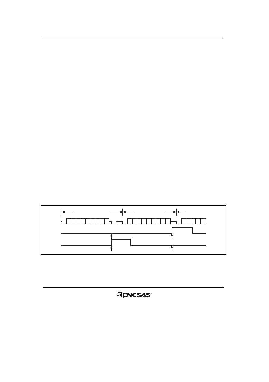 Section 19 Serial Communication Interface (SCI, IrDA, CRC) Rev. 2.00 Sep. 24, 2008 Page 944 of 1468 REJ09B0412-0200 19.7.7 Serial Data Reception (Except in Block Transfer Mode) Data reception in smart card interface mode is similar to that in normal serial communication interface mode. Figure 19.32 shows the data re-transfer operation during reception. 1. If a parity error is detected in receive data, the PER bit in SSR is set to 1. Here, an ERI interrupt request is generated if the RIE bit in SCR is set to 1. Clear the PER bit to 0 before the next parity bit is sampled. 2. For the frame in which a parity error is detected, the RDRF bit in SSR is not set to 1. 3. If no parity error is detected, the PER bit in SSR is not set to 1. 4. In this case, data is determined to have been received successfully, and the RDRF bit in SSR is set to 1. Here, an RXI interrupt request is generated if the RIE bit in SCR is set to 1. Figure 19.33 shows a sample flowchart for reception. All the processing steps are automatically performed using an RXI interrupt request to activate the DTC or DMAC. In reception, setting the RIE bit to 1 allows an RXI interrupt request to be generated when the RDRF flag is set to 1. This activates the DTC or DMAC by an RXI request thus allowing transfer of receive data if the RXI interrupt request is specified as a source of DTC or DMAC activation beforehand. The RDRF flag is automatically cleared to 0 at data transfer by the DTC or DMAC. If an error occurs during reception, i.e., either the ORER or PER flag is set to 1, a transmit/receive error interrupt (ERI) request is generated and the error flag must be cleared. If an error occurs, the DTC or DMAC is not activated and receive data is skipped, therefore, the number of bytes of receive data specified in the DTC or DMAC is transferred. Even if a parity error occurs and the PER bit is set to 1 in reception, receive data is transferred to RDR, thus allowing the data to be read. Note: For operations in block transfer mode, see section 19.4, Operation in Asynchronous Mode. D0 D1 D2 D3 D4 D5 D6 D7 Dp DE Ds D0 D1 D2 D3 D4 D5 D6 D7 Dp (DE) Ds D0 D1 D2 D3 D4 Ds (n + 1) th transfer frame Retransfer frame nth transfer frame RDRF [1] PER [2] [3] [4] Figure 19.32 Data Re-Transfer Operation in SCI Reception Mode |
|
Link URL |
| Does ALLDATASHEET help your business so far? [ DONATE ] |
About Alldatasheet | Advertisement | Contact us | Privacy Policy | Link to Datasheet | Link Exchange | Manufacturer List All Rights Reserved©Alldatasheet.com |
| Russian : Alldatasheetru.com | Korean : Alldatasheet.co.kr | Spanish : Alldatasheet.es | French : Alldatasheet.fr | Italian : Alldatasheetit.com Portuguese : Alldatasheetpt.com | Polish : Alldatasheet.pl | Vietnamese : Alldatasheet.vn Indian : Alldatasheet.in | Mexican : Alldatasheet.com.mx | British : Alldatasheet.co.uk | New Zealand : Alldatasheet.co.nz |
|
Family Site : ic2ic.com |
icmetro.com |
 British ▼
 English
 Chinese
 German
 Japanese
 Russian
 Korean
 Spanish
 French
 Italian
 Portuguese
 Polish
 Vietnamese
 Indian
 Mexican
 British
 New Zealand


