 |
Electronic Components Datasheet Search |
|
|
Electronic Components Datasheet Search |
|
H8SX/1663R Datasheet(PDF) 1201 Page - Renesas Technology Corp |
|
|
|||||||||||||||||||||||||||||
H8SX/1663R Datasheet(HTML) 1201 Page - Renesas Technology Corp |
|
|
1201 / 1504 page 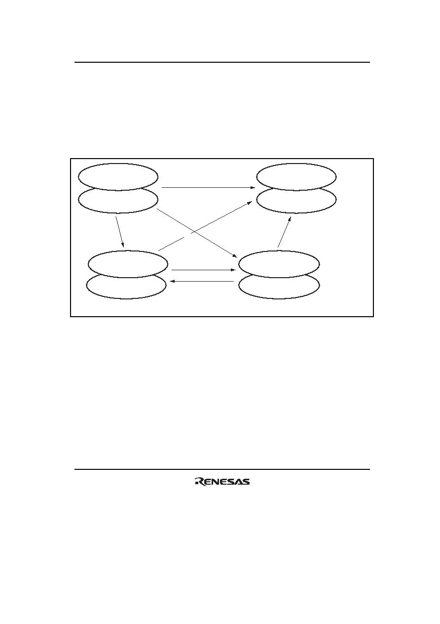 Section 25 Flash Memory Rev. 2.00 Sep. 24, 2008 Page 1169 of 1468 REJ09B0412-0200 Error protection is canceled by a reset. Note that the reset should be released after the reset input period of at least 100 µs has passed. Since high voltages are applied during programming/erasure of the flash memory, some voltage may remain after the error protection state has been entered. For this reason, it is necessary to reduce the risk of damaging the flash memory by extending the reset input period so that the charge is released. The state-transition diagram in figure 25.18 shows transitions to and from the error protection state. Reset (hardware protection) Programming/erasing mode Error-protection mode Error-protection mode (software standby) Read disabled Programming/erasing enabled FLER = 0 Read disabled Programming/erasing disabled FLER = 0 Read enabled Programming/erasing disabled FLER = 1 Read disabled Programming/erasing disabled FLER = 1 RES = 0 Error occurrence Error occurred (Software standby) RES = 0 Software standby mode Cancel software standby mode RES = 0 Programming/erasing interface register is in its initial state. Programming/erasing interface register is in its initial state. Figure 25.18 Transitions to Error Protection State |
|
Link URL |
| Does ALLDATASHEET help your business so far? [ DONATE ] |
About Alldatasheet | Advertisement | Contact us | Privacy Policy | Link to Datasheet | Link Exchange | Manufacturer List All Rights Reserved©Alldatasheet.com |
| Russian : Alldatasheetru.com | Korean : Alldatasheet.co.kr | Spanish : Alldatasheet.es | French : Alldatasheet.fr | Italian : Alldatasheetit.com Portuguese : Alldatasheetpt.com | Polish : Alldatasheet.pl | Vietnamese : Alldatasheet.vn Indian : Alldatasheet.in | Mexican : Alldatasheet.com.mx | British : Alldatasheet.co.uk | New Zealand : Alldatasheet.co.nz |
|
Family Site : ic2ic.com |
icmetro.com |
 British ▼
 English
 Chinese
 German
 Japanese
 Russian
 Korean
 Spanish
 French
 Italian
 Portuguese
 Polish
 Vietnamese
 Indian
 Mexican
 British
 New Zealand


