|
Electronic Components Datasheet Search |
|
|
Electronic Components Datasheet Search |
|
AS29F040CW-120/Q Datasheet(PDF) 6 Page - Austin Semiconductor |
|
|
|||||||||||||||||||||||||||||
AS29F040CW-120/Q Datasheet(HTML) 6 Page - Austin Semiconductor |
|
|
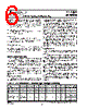
6 / 27 page  FLASH FLASH FLASH FLASH FLASH AS29F040 AustinSemiconductor,Inc.reservestherighttochangeproductsorspecificationswithoutnotice. 6 AS29F040 Rev. 2.2 09/07 Austin Semiconductor, Inc. power-down. The command register and all internal program/ erase circuits are disabled, and the device resets. Subsequent writes are ignored until V CC is greater than V LKO . The system must provide the proper signals to the control pins to prevent unintentional writes when V CC is greater than V LKO . Write Pulse “Glitch” Protection Noise pulses of less than 5ns (typical) on OE\, CE\, or WE\ do not initiate a write cycle. Logical Inhibit Write cycles are inhibited by holding any one of OE\ = V IL , CE\ = V IH or WE\ = V IH . To initiate a write cycle, CE\ and WE\ must be a logical zero while OE\ is a logical one. Power-Up Write Inhibit If WE\ = CE\ = V IL and OE\ = V IH during power up, the device does not accept commands on the rising edge of WE\. The internal state machine is automatically reset to reading array data on power-up. COMMAND DEFINITIONS Writing specific address and data commands or sequences into the command register initiates device operations. The Command Definitions table defines the valid register command sequences. Writing incorrect address and data values or writing them in the improper sequence resets the device to reading array data. All addresses are latched on the falling edge of WE\ or CE\, whichever happens later. All data is latched on the rising edge of WE\ or CE\, whichever happens first. Refer to the appropriate timing diagrams in the “AC Characteristics” section. Reading Array Data The device is automatically set to reading array data after device power-up. No commands are required to retrieve data. TABLE 3: Autoselect Codes (High Voltage Method) The device is also ready to read array data after completing an Embedded Program or Embedded Erase algorithm. After the device accepts an Erase Suspend command, the device enters the Erase Suspend mode. The system can read array data using the standard read timings, except that if it reads at an address within erase-suspended sectors, the device outputs status data. After completing a programming operation in the Erase Suspend mode, the system may once again read array data with the same exception. See “Erase Suspend/Erase Resume” for more information. The system must issue the reset command to re-enable the device for reading array data if DQ5 goes high, or while in the autoselect mode. See the “Reset Command” section, next. See also “Requirements for Reading Array Data” in the “Device Bus Operations” section for more information. The Read Operations table provides the read parameters, and the Read Operation Timings diagram shows the timing diagram. Reset Command Writing the reset command to the device resets the device to reading array data. Address bits are don’t care for this command. The reset command may be written between the sequence cycles in an erase command sequence before erasing begins. This resets the device to reading array data. Once erasure begins, however, the device ignores reset commands until the operation is complete. The reset command may be written between the sequence cycles in a program command sequence before programming begins. This resets the device to reading array data (also applies to programming in Erase Suspend Mode). Once programming begins, however, the device ignores reset commands until the operation is complete. The reset command may be written between the sequence cycles in an autoselect command sequence. Once in the autoselect mode, the reset command must be written to return to reading array data (also applies to autoselect during Erase Suspend). Description A18 - A16 A15 - A10 A9 A8 - A7 A6 A5 - A2 A1 A0 Identifier Code On DQ7 to DQ0 Manufacturer ID X X VID X VIL X VIL VIL 01h Device ID X X VID X VIL X VIL VIH A4h 01h (protected) 00h (unprotected) Sector Protection Verification Sector Address XVID XVIL XVIH VIL |
|
Link URL |
| Does ALLDATASHEET help your business so far? [ DONATE ] |
About Alldatasheet | Advertisement | Contact us | Privacy Policy | Link to Datasheet | Link Exchange | Manufacturer List All Rights Reserved©Alldatasheet.com |
| Russian : Alldatasheetru.com | Korean : Alldatasheet.co.kr | Spanish : Alldatasheet.es | French : Alldatasheet.fr | Italian : Alldatasheetit.com Portuguese : Alldatasheetpt.com | Polish : Alldatasheet.pl | Vietnamese : Alldatasheet.vn Indian : Alldatasheet.in | Mexican : Alldatasheet.com.mx | British : Alldatasheet.co.uk | New Zealand : Alldatasheet.co.nz |
|
Family Site : ic2ic.com |
icmetro.com |
 British ▼
 English
 Chinese
 German
 Japanese
 Russian
 Korean
 Spanish
 French
 Italian
 Portuguese
 Polish
 Vietnamese
 Indian
 Mexican
 British
 New Zealand