|
Electronic Components Datasheet Search |
|
|
Electronic Components Datasheet Search |
|
RF5755 Datasheet(PDF) 11 Page - RF Micro Devices |
|
|
|||||||||||||||||||||||||||||
RF5755 Datasheet(HTML) 11 Page - RF Micro Devices |
|
|
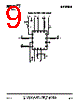
11 / 15 page  11 of 15 RF5755 DS120214 7628 Thorndike Road, Greensboro, NC 27409-9421 · For sales or technical support, contact RFMD at (+1) 336-678-5570 or sales-support@rfmd.com. WiFi and BLUETOOTH® RECEIVE (SIMULTANEOUS MODE) The RF755 WiFi and Bluetooth® receive circuits were specifically designed to address issues of simultaneous operation. In this mode both signals can be received at the same time when the C_BWRX (pin-16) is set high. The typical gain for each RF path is approximately 13dB and a NF of 3dB. During simultaneous mode the active components are the LNA, the SPST switch, and only the Rx branch of the SP3T. Refer to the logic control table for proper settings. Simultaneous Mode Biasing Instructions • Connect the RF input (ANT/pin-11) to a signal generator and a spectrum analyzer at the RX (pin-2) and BT (pin-13) RF ports. A multiport VNA may be used as well. • Turn the LNA bias on (pin-1) and set the voltage to 3.3V. • Set C_RX (pin-15) and C_BWRX (pin-16) high. This turns on the receive branch of the SP3T and the SPST switch. • The SP3T controls for the off branches (VREG and C_BT) must be set to a logic “low” (0.2V max) or grounded. In the event that one of these branches is left floating or in a logic “high” the performance will degrade. It is recommended to termi- nate unused RF Ports in 50Ω. •Turn RF on. BLUETOOTH® MODE The RF755 Bluetooth® only mode is implemented through the SP3T switch by setting C_BT “high.” Typical insertion loss is about 1.2dB. Bluetooth® Biasing Instructions • Connect the RF input (ANT/pin-11) to a signal generator and a spectrum analyzer at the BT (pin-13) RF port. A VNA may be used in place of the signal generator and SA. • Set C_BT (pin-12) “high.” This turns the Bluetooth® branch of the SP3T switch on. • The SP3T controls for the off branches (VREG and C_RX) must be set to a logic “low” (0.2V max) or grounded. Do not leave floating. • Terminate unused RF Ports in 50Ω. •Turn RF on. APPLICATION CIRCUIT AND LAYOUT RECOMMENDATIONS The RF5755 integrates the matching networks and DC blocking capacitors for all RF ports. This greatly reduces the number of external components and layout area needed to implement this FEM. Typically only a total of four external components are required to achieve nominal performance. However, depending on board layout and the many noise signals that could poten- tially couple to the RF5755, additional bypassing capacitors may be required to properly filter out unwanted signals that might degrade performance. The LNA bias components consist of an inductor and a decoupling capacitor. The inductor value is critical to optimize NF and return loss at the Rx output. For best performance and trade off between critical parameters such as NF, Gain, and IP3, the total inductance including board trace should be approximately 1.2nH. The 5.6kΩ series resistor for the Bluetooth® control line helps to prevent unwanted signals from coupling to this pin. The resistor should be placed as close as possible to the pack- age pin. The last component needed in the application circuit is a low frequency bypass capacitor on the VCC line. In general, it is good RF practice to have proper decoupling of supply lines to filter out noise. Occasionally, depending on the level of cou- pling or parasitics of the board, a high frequency bypass capacitor must be added as well. In order to optimize performance for both the Transmit and Receive paths, a good layout design must be implemented. As it is well know in the RF world, any mismatch and off port loading affects performance. To minimize this effect and have a more robust layout, all RF traces must be 50Ω. Adequate grounding along the RF traces and on the FEM ground slug must be exer- |
|
|
Link URL |
| Does ALLDATASHEET help your business so far? [ DONATE ] |
About Alldatasheet | Advertisement | Contact us | Privacy Policy | Link to Datasheet | Link Exchange | Manufacturer List All Rights Reserved©Alldatasheet.com |
| Russian : Alldatasheetru.com | Korean : Alldatasheet.co.kr | Spanish : Alldatasheet.es | French : Alldatasheet.fr | Italian : Alldatasheetit.com Portuguese : Alldatasheetpt.com | Polish : Alldatasheet.pl | Vietnamese : Alldatasheet.vn Indian : Alldatasheet.in | Mexican : Alldatasheet.com.mx | British : Alldatasheet.co.uk | New Zealand : Alldatasheet.co.nz |
|
Family Site : ic2ic.com |
icmetro.com |
 British ▼
 English
 Chinese
 German
 Japanese
 Russian
 Korean
 Spanish
 French
 Italian
 Portuguese
 Polish
 Vietnamese
 Indian
 Mexican
 British
 New Zealand