|
Electronic Components Datasheet Search |
|
|
Electronic Components Datasheet Search |
|
7531 Datasheet(PDF) 3 Page - Mallory performance club |
|
|
|||||||||||||||||||||||||||||
7531 Datasheet(HTML) 3 Page - Mallory performance club |
|
|
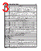
3 / 20 page  INSTALLATION INSTRUCTIONS 3 MSD • W W W. M S D PE R F OR M A NC E . C OM • ( 91 5 ) 8 57 - 5 20 0 • F AX ( 91 5 ) 8 57 - 33 4 4 Limit Lt Green Accessories Dark Blue This wire activates the Launch Rev Limit and is the main reset wire for several features of the Ignition. When 12 volts are applied to this wire it will activate the Launch Rev Limit. It also resets the shift light and gear indicator to first gear. It also will select the Launch Retard value and Gear 1 curve. When 12 volts is removed, the Launch Ramp begins as does the Gear 1 curve. When12 volts are applied the Slew Rate Rev limit will be disabled as well as the Timed Rev Limit curve. When 12 volts are removed the Launch History begins recording. Light Blue Burnout Rev Limit. When 12 volts are applied the Burnout Rev Limit is active. This disables the Acquisition function and Slew Rate Rev Limits and overrides other rev limits. It also resets the Acquisition Record function. It is recommended to have this wire switched from an outside source, such as the crew chief before the burnout and while staging the car. Spool-Up When the Dark Blue and Light Blue wires are applied to 12 volts at the same time, a fourth rev limit is activated. This limit is to spool up a turbo during the burnout. When both the Dark Blue and Light Blue RevLimit wires are at +12 volts then the Spool RevLimit is active. Retard Stage Wires or Gear Select These three wires can be used as Retard Stage Activation and/or as a gear select wire. Pink Step1 retard enabled with +12 volt input and above Step1 Rpm value and Gear 2 Select. Violet Step2 retard enabled with +12 volt input and above Step2 Rpm value and Gear 3 Select. Tan Step3 retard enabled with +12 volt input and above Step3 Rpm value and Gear 4 Select. Note: When activated at the same time, these retard stages are added together. They are also added with any Gear Retard Curve or Boost Retard values as well. Maximum retard is 30°. Yellow Shift Light output wire. It can handle up to 3 amps continuous to ground when enabled. Brown/White RPM/Time/Pressure switch output wire. It can switch up to 3 amps continuous to ground when enabled. Yellow/Yellow Output for data acquisition or fuel controls. Note, only two wires are used. 3-Pin Connector, MAP Sensor Connector Connects to an external MAP or gauge pressure sensor. Brown/Violet +5 volt supply Brown/Yellow Ground Dark Brown Map Signal Cam Synchronization Fiber Optic This input requires the PN 7555 Inductive Sync Pickup. When this input is used, the 2-pin con- nector is not. Note: If this input is not used, the plug or a cover should be installed. 2-Pin Connector Lt Blue/ This 2-pin plug connects to Cam Sync Sensor, PN 2346, to indicate when cylinder number one is firing. Note: When used, the fiber optic connector is not used and must be covered. |
|
|
Link URL |
| Does ALLDATASHEET help your business so far? [ DONATE ] |
About Alldatasheet | Advertisement | Contact us | Privacy Policy | Link to Datasheet | Link Exchange | Manufacturer List All Rights Reserved©Alldatasheet.com |
| Russian : Alldatasheetru.com | Korean : Alldatasheet.co.kr | Spanish : Alldatasheet.es | French : Alldatasheet.fr | Italian : Alldatasheetit.com Portuguese : Alldatasheetpt.com | Polish : Alldatasheet.pl | Vietnamese : Alldatasheet.vn Indian : Alldatasheet.in | Mexican : Alldatasheet.com.mx | British : Alldatasheet.co.uk | New Zealand : Alldatasheet.co.nz |
|
Family Site : ic2ic.com |
icmetro.com |
 British ▼
 English
 Chinese
 German
 Japanese
 Russian
 Korean
 Spanish
 French
 Italian
 Portuguese
 Polish
 Vietnamese
 Indian
 Mexican
 British
 New Zealand