Electronic Components Datasheet Search
  British  ▼
ALLDATASHEET.CO.UK

X  

MAX2323 Datasheet with Chat AI
  • AIauthorized

    Hello, Please ask a question about MAX2323 Datasheet

  • # Example questions: ➢ What are the primary control pins (mode, g1, g2, sleep) needed to configure the max2323/max2325 for cellular band, cdma mode, high gain, and high linearity?
    ➢ How does the rbias pin affect the linearity of the lna and mixers in the max2323/max2325, and in which modes is it *not* applicable?
    ➢ What control pin settings are required to shut down the max2323?

  • Part No.MAX2323
    ManufacturerMAXIM
    Size164 Kbytes
    Pages14 pages
    DescriptionTriple/Dual-Mode CDMA LNA/Mixers
    Datasheet Summary with AI

    1. Overview

    ️· MAX2323: A dual-band (PCS/Cellular), triple-mode (LNA/Mixer) device targeting CDMA applications. It’s intended to combine LNA and mixer functionality into a single chip.
    ️· MAX2325: A dual-band (PCS/Cellular), triple-mode (LNA/Mixer) device targeting CDMA applications. Similar in concept to the MAX2323, but with some pin differences and operational mode variations.

    2. Key Features

    ️· Dual-Band Support: Operates in both PCS (Personal Communications Services) and Cellular frequency bands. This is selectable.
    ️· Triple-Mode Operation: Functionality as an LNA (Low Noise Amplifier), Mixer, and LNA/Mixer combination.
    ️· Multiple Gain Options: High Gain, Midgain, and Low Gain settings.
    ️· Linearity Control: Adjustable linearity, important for CDMA signals. The ability to prioritize gain versus linearity.
    ️· Shutdown Mode: Power saving feature.
    ️· Logic Control: Extensive use of control pins (G1, G2, MODE, SLEEP, BAND) to configure the device.
    ️· Compact Design: Integrating multiple functions reduces board space.

    3. Operational Modes (Summary & Key Differences)

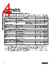
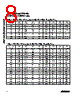
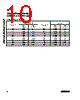
    The tables in the datasheet provide the operational modes. Here's a summarized view of what each mode is doing and the relevant control signals:

    Feature MAX2323 MAX2325
    Band Selection BAND Pin Not explicitly stated, potentially internal
    Gain Selection HGHL, HGLL, MGHL, LGHL HGHL, HGLL, MGHL, LGHL
    Mode Selection G1, G2, MODE G1, G2, SLEEP
    Shutdown SLEEP = 1 SLEEP = 1

    Specific Mode Examples (Illustrative)

    ️· PCS Band, High Gain, High Linearity (HGHL): Used for optimal performance in the PCS band where high sensitivity and minimal distortion are critical.
    - MAX2323: BAND=P, G1=0, G2=0, MODE=0, SLEEP=0
    - MAX2325: BAND=N/A, G1=0, G2=0, SLEEP=0
    ️· Cellular Band, CDMA Mode, Low Gain (LGHL): Favored in situations where power consumption is a greater concern than maximum sensitivity.
    - MAX2323: BAND=C, G1=1, G2=1, MODE=0, SLEEP=0
    - MAX2325: BAND=N/A, G1=1, G2=1, SLEEP=0

    Important Notes on Operational Modes:

    ️· The control pin combinations are *critical* to selecting the desired mode. Consult the tables for specific configurations.
    ️· "Undefined" modes (shown in the MAX2325 datasheet) are not guaranteed to work as expected. Avoid using them.
    ️· The datasheet highlights modes specific to "FM Mode" – these are used for FM radio functionality within the device.

    4. Pinouts (Key Pins)

    Pin MAX2323 MAX2325 Description
    BAND Yes No (Internally selected) Selects between Cellular and PCS bands
    G1, G2 Yes Yes Logic control pins for mode selection
    MODE Yes No (Replaced by SLEEP) Logic control pin for mode selection
    SLEEP Yes Yes Shutdown control
    CLNAIN Yes Yes Low-band RF input
    PLNAOUT Yes Yes High-band LNA output
    CMIXIN Yes Yes Low-band mixer input
    PMIXIN Yes Yes High-band mixer input
    VCC Yes Yes Power supply (2.7V - 3.6V)
    RBIAS Yes Yes Bias setting pin
    GND Yes Yes Ground


    5. Important Considerations

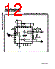
    ️· Matching Networks: The datasheets repeatedly mention the need for external matching networks at various RF input and output pins (CLNAIN, PLNAOUT, CMIXIN, PMIXIN). These are *essential* for optimal performance.
    ️· Bypass Capacitors: Placement of bypass capacitors near the VCC pin is required for stable operation.
    ️· Control Pin Logic Levels: Ensure proper logic levels are applied to the control pins.
    ️· Application-Specific Requirements: The best mode selection depends on the specific application and its priorities (linearity vs. gain vs. power consumption).

    6. Differences Between MAX2323 and MAX2325

    ️· Control Pin Differences: The MAX2325 replaces the MODE pin found in the MAX2323 with the SLEEP pin.
    ️· Band Selection: The MAX2323 has a BAND pin that is used to select the band, while the MAX2325 selects the band internally.

    1. Overview

    ️· MAX2323: A dual-band (PCS/Cellular), triple-mode (LNA/Mixer) device targeting CDMA applications. It’s intended to combine LNA and mixer functionality into a single chip.
    ️· MAX2325: A dual-band (PCS/Cellular), triple-mode (LNA/Mixer) device targeting CDMA applications. Similar in concept to the MAX2323, but with some pin differences and operational mode variations.

    2. Key Features

    ️· Dual-Band Support: Operates in both PCS (Personal Communications Services) and Cellular frequency bands. This is selectable.
    ️· Triple-Mode Operation: Functionality as an LNA (Low Noise Amplifier), Mixer, and LNA/Mixer combination.
    ️· Multiple Gain Options: High Gain, Midgain, and Low Gain settings.
    ️· Linearity Control: Adjustable linearity, important for CDMA signals. The ability to prioritize gain versus linearity.
    ️· Shutdown Mode: Power saving feature.
    ️· Logic Control: Extensive use of control pins (G1, G2, MODE, SLEEP, BAND) to configure the device.
    ️· Compact Design: Integrating multiple functions reduces board space.

    3. Operational Modes (Summary & Key Differences)

    The tables in the datasheet provide the operational modes. Here's a summarized view of what each mode is doing and the relevant control signals:

    Feature MAX2323 MAX2325
    Band Selection BAND Pin Not explicitly stated, potentially internal
    Gain Selection HGHL, HGLL, MGHL, LGHL HGHL, HGLL, MGHL, LGHL
    Mode Selection G1, G2, MODE G1, G2, SLEEP
    Shutdown SLEEP = 1 SLEEP = 1

    Specific Mode Examples (Illustrative)

    ️· PCS Band, High Gain, High Linearity (HGHL): Used for optimal performance in the PCS band where high sensitivity and minimal distortion are critical.
    - MAX2323: BAND=P, G1=0, G2=0, MODE=0, SLEEP=0
    - MAX2325: BAND=N/A, G1=0, G2=0, SLEEP=0
    ️· Cellular Band, CDMA Mode, Low Gain (LGHL): Favored in situations where power consumption is a greater concern than maximum sensitivity.
    - MAX2323: BAND=C, G1=1, G2=1, MODE=0, SLEEP=0
    - MAX2325: BAND=N/A, G1=1, G2=1, SLEEP=0

    Important Notes on Operational Modes:

    ️· The control pin combinations are *critical* to selecting the desired mode. Consult the tables for specific configurations.
    ️· "Undefined" modes (shown in the MAX2325 datasheet) are not guaranteed to work as expected. Avoid using them.
    ️· The datasheet highlights modes specific to "FM Mode" – these are used for FM radio functionality within the device.

    4. Pinouts (Key Pins)

    Pin MAX2323 MAX2325 Description
    BAND Yes No (Internally selected) Selects between Cellular and PCS bands
    G1, G2 Yes Yes Logic control pins for mode selection
    MODE Yes No (Replaced by SLEEP) Logic control pin for mode selection
    SLEEP Yes Yes Shutdown control
    CLNAIN Yes Yes Low-band RF input
    PLNAOUT Yes Yes High-band LNA output
    CMIXIN Yes Yes Low-band mixer input
    PMIXIN Yes Yes High-band mixer input
    VCC Yes Yes Power supply (2.7V - 3.6V)
    RBIAS Yes Yes Bias setting pin
    GND Yes Yes Ground


    5. Important Considerations

    ️· Matching Networks: The datasheets repeatedly mention the need for external matching networks at various RF input and output pins (CLNAIN, PLNAOUT, CMIXIN, PMIXIN). These are *essential* for optimal performance.
    ️· Bypass Capacitors: Placement of bypass capacitors near the VCC pin is required for stable operation.
    ️· Control Pin Logic Levels: Ensure proper logic levels are applied to the control pins.
    ️· Application-Specific Requirements: The best mode selection depends on the specific application and its priorities (linearity vs. gain vs. power consumption).

    6. Differences Between MAX2323 and MAX2325

    ️· Control Pin Differences: The MAX2325 replaces the MODE pin found in the MAX2323 with the SLEEP pin.
    ️· Band Selection: The MAX2323 has a BAND pin that is used to select the band, while the MAX2325 selects the band internally.

    Part No.MAX2323
    ManufacturerMAXIM
    Size164 Kbytes
    Pages14 pages
    DescriptionTriple/Dual-Mode CDMA LNA/Mixers
    Does ALLDATASHEET help your business so far?  [ DONATE ] 

    About Alldatasheet   |   Advertisement   |   Contact us   |   Privacy Policy   |   Link to Datasheet    |   Link Exchange   |   Manufacturer List
    All Rights Reserved©Alldatasheet.com


    Mirror Sites
    English : Alldatasheet.com  |   English : Alldatasheet.net  |   Chinese : Alldatasheetcn.com  |   German : Alldatasheetde.com  |   Japanese : Alldatasheet.jp
    Russian : Alldatasheetru.com  |   Korean : Alldatasheet.co.kr  |   Spanish : Alldatasheet.es  |   French : Alldatasheet.fr  |   Italian : Alldatasheetit.com
    Portuguese : Alldatasheetpt.com  |   Polish : Alldatasheet.pl  |   Vietnamese : Alldatasheet.vn
    Indian : Alldatasheet.in  |   Mexican : Alldatasheet.com.mx  |   British : Alldatasheet.co.uk  |   New Zealand : Alldatasheet.co.nz
    Family Site : ic2ic.com  |   icmetro.com