|
Electronic Components Datasheet Search |
|
|
Electronic Components Datasheet Search |
|
ADP5072ACBZ-R7 Datasheet(PDF) 23 Page - Analog Devices |
|
|
|||||||||||||||||||||||||||||
ADP5072ACBZ-R7 Datasheet(HTML) 23 Page - Analog Devices |
|
|
23 / 24 page 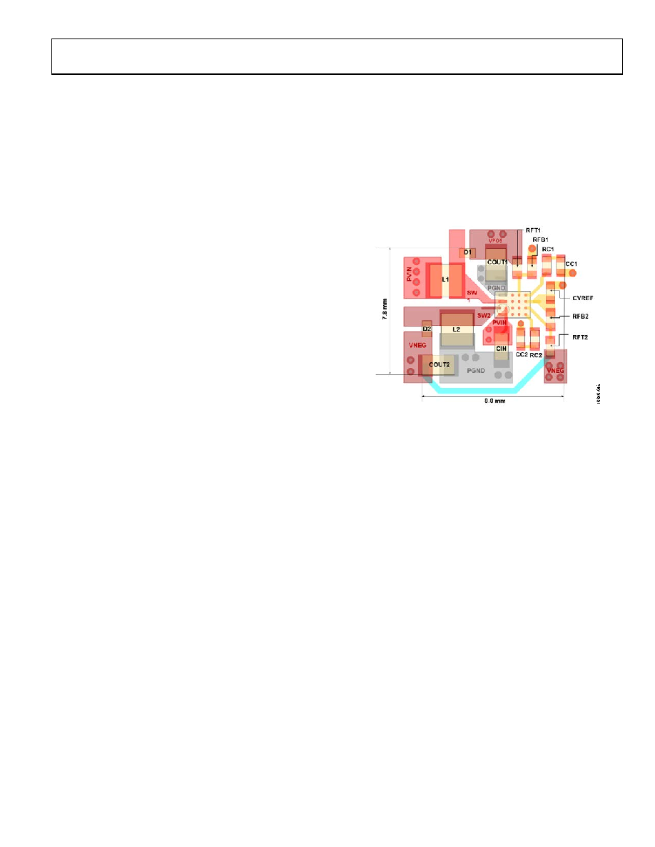 Data Sheet ADP5072 Rev. 0 | Page 23 of 24 LAYOUT CONSIDERATIONS Layout is important for all switching regulators but is particularly important for regulators with high switching frequencies. To achieve high efficiency, proper regulation, stability, and low noise, a well designed PCB layout is required. Follow these guidelines when designing PCBs (see Figure 48): • Keep the input bypass capacitor, CIN, close to the PVIN pin and the AVIN pin. • Keep the high current paths as short as possible. These paths include the connections between the following: • CIN, L1, D1, COUT1, and PGND for the boost regulator, the connections • L2, D2, COUT2, and PGND for the inverting regulator • The connections of these components for both the boost and inverting regulators to the ADP5072. • Keep AGND and PGND separate on the top layer of the board. This separation avoids pollution of AGND with switching noise. Connect both AGND and PGND to the board ground plane with vias. Ideally, connect PGND to the plane at a point between the input and output capacitors. • Keep high current traces as short and wide as possible to minimize parasitic series inductance, which causes spiking and EMI. • Avoid routing high impedance traces near any node con- nected to the SW1 and SW2 pins or near Inductors L1and L2 to prevent radiated switching noise injection. • Place the feedback resistors as close to the FB1 and FB2 pins as possible to prevent high frequency switching noise injection. • Place the top of the upper feedback resistors, RFT1 and RFT2, as close as possible to the top of COUT1 and COUT2 for optimum output voltage sensing, or route traces to the RFT1 and RFT2 resistors as close as possible from the top of COUT1 and COUT2. • Place the compensation components as close as possible to COMP1 and COMP2. Do not share vias to the ground plane with the feedback resistors to avoid coupling high frequency noise into the sensitive COMP1 and COMP2 pins. • Place the CVREF capacitor as close to the VREF pin as possible. Ensure that short traces are used between VREF and RFB2. Figure 48. Suggested Layout for VIN = 3.3 V, VPOS = 12 V, ILOAD1 = 100 mA and VNEG = −3.2 V, ILOAD2 = 60 mA; Not to Scale |
|
|
Link URL |
| Does ALLDATASHEET help your business so far? [ DONATE ] |
About Alldatasheet | Advertisement | Contact us | Privacy Policy | Link to Datasheet | Link Exchange | Manufacturer List All Rights Reserved©Alldatasheet.com |
| Russian : Alldatasheetru.com | Korean : Alldatasheet.co.kr | Spanish : Alldatasheet.es | French : Alldatasheet.fr | Italian : Alldatasheetit.com Portuguese : Alldatasheetpt.com | Polish : Alldatasheet.pl | Vietnamese : Alldatasheet.vn Indian : Alldatasheet.in | Mexican : Alldatasheet.com.mx | British : Alldatasheet.co.uk | New Zealand : Alldatasheet.co.nz |
|
Family Site : ic2ic.com |
icmetro.com |
 British ▼
 English
 Chinese
 German
 Japanese
 Russian
 Korean
 Spanish
 French
 Italian
 Portuguese
 Polish
 Vietnamese
 Indian
 Mexican
 British
 New Zealand