|
Electronic Components Datasheet Search |
|
|
Electronic Components Datasheet Search |
|
STGB15M65DF2 Datasheet(PDF) 5 Page - STMicroelectronics |
|
|
|||||||||||||||||||||||||||||
STGB15M65DF2 Datasheet(HTML) 5 Page - STMicroelectronics |
|
|
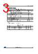
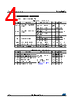
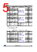
5 / 19 page  STGB15M65DF2 Electrical characteristics DocID025356 Rev 4 5/19 Table 6: IGBT switching characteristics (inductive load) Symbol Parameter Test conditions Min. Typ. Max. Unit td(on) Turn-on delay time VCE = 400 V, IC = 15 A, VGE = 15 V, RG = 12 Ω (see Figure 29: " Test circuit for inductive load switching" ) 24 - ns tr Current rise time 7.8 - ns (di/dt)on Turn-on current slope 1570 - A/µs td(off) Turn-off-delay time 93 - ns tf Current fall time 106 - ns Eon(1) Turn-on switching energy 0.09 - mJ Eoff(2) Turn-off switching energy 0.45 - mJ Ets Total switching energy 0.54 - mJ td(on) Turn-on delay time VCE = 400 V, IC = 15 A, VGE = 15 V, RG = 12 Ω, TJ = 175 °C (see Figure 29: " Test circuit for inductive load switching" ) 24.8 - ns tr Current rise time 9.2 - ns (di/dt)on Turn-on current slope 1300 - A/µs td(off) Turn-off-delay time 96 - ns tf Current fall time 169 - ns Eon(1) Turn-on switching energy 0.22 - mJ Eoff(2) Turn-off switching energy 0.61 - mJ Ets Total switching energy 0.83 - mJ tsc Short-circuit withstand time VCC ≤ 400 V, VGE = 15 V, TJstart = 150 °C 6 - µs VCC ≤ 400 V, VGE = 13 V, TJstart = 150 °C 10 Notes: (1)Including the reverse recovery of the diode. (2)Including the tail of the collector current. Table 7: Diode switching characteristics (inductive load) Symbol Parameter Test conditions Min. Typ. Max. Unit trr Reverse recovery time IF = 15 A, VR = 400 V, VGE = 15 V, di/dt = 1000 A/µs (see Figure 29: " Test circuit for inductive load switching") - 142 - ns Qrr Reverse recovery charge - 525 - nC Irrm Reverse recovery current - 13.4 - A dIrr/dt Peak rate of fall of reverse recovery current during tb - 790 - A/µs Err Reverse recovery energy - 64 - µJ trr Reverse recovery time IF = 15 A, VR = 400 V, VGE = 15 V, di/dt = 1000 A/µs, TJ = 175 °C (see Figure 29: " Test circuit for inductive load switching") - 241 - ns Qrr Reverse recovery charge - 1690 - nC Irrm Reverse recovery current - 20 - A dIrr/dt Peak rate of fall of reverse recovery current during tb - 420 - A/µs Err Reverse recovery energy - 176 - µJ |
|
|
Link URL |
| Does ALLDATASHEET help your business so far? [ DONATE ] |
About Alldatasheet | Advertisement | Contact us | Privacy Policy | Link to Datasheet | Link Exchange | Manufacturer List All Rights Reserved©Alldatasheet.com |
| Russian : Alldatasheetru.com | Korean : Alldatasheet.co.kr | Spanish : Alldatasheet.es | French : Alldatasheet.fr | Italian : Alldatasheetit.com Portuguese : Alldatasheetpt.com | Polish : Alldatasheet.pl | Vietnamese : Alldatasheet.vn Indian : Alldatasheet.in | Mexican : Alldatasheet.com.mx | British : Alldatasheet.co.uk | New Zealand : Alldatasheet.co.nz |
|
Family Site : ic2ic.com |
icmetro.com |
 British ▼
 English
 Chinese
 German
 Japanese
 Russian
 Korean
 Spanish
 French
 Italian
 Portuguese
 Polish
 Vietnamese
 Indian
 Mexican
 British
 New Zealand