|
Electronic Components Datasheet Search |
|
|
Electronic Components Datasheet Search |
|
AT89C5132-ROTIL Datasheet(PDF) 133 Page - ATMEL Corporation |
|
|
|||||||||||||||||||||||||||||
AT89C5132-ROTIL Datasheet(HTML) 133 Page - ATMEL Corporation |
|
|
133 / 181 page 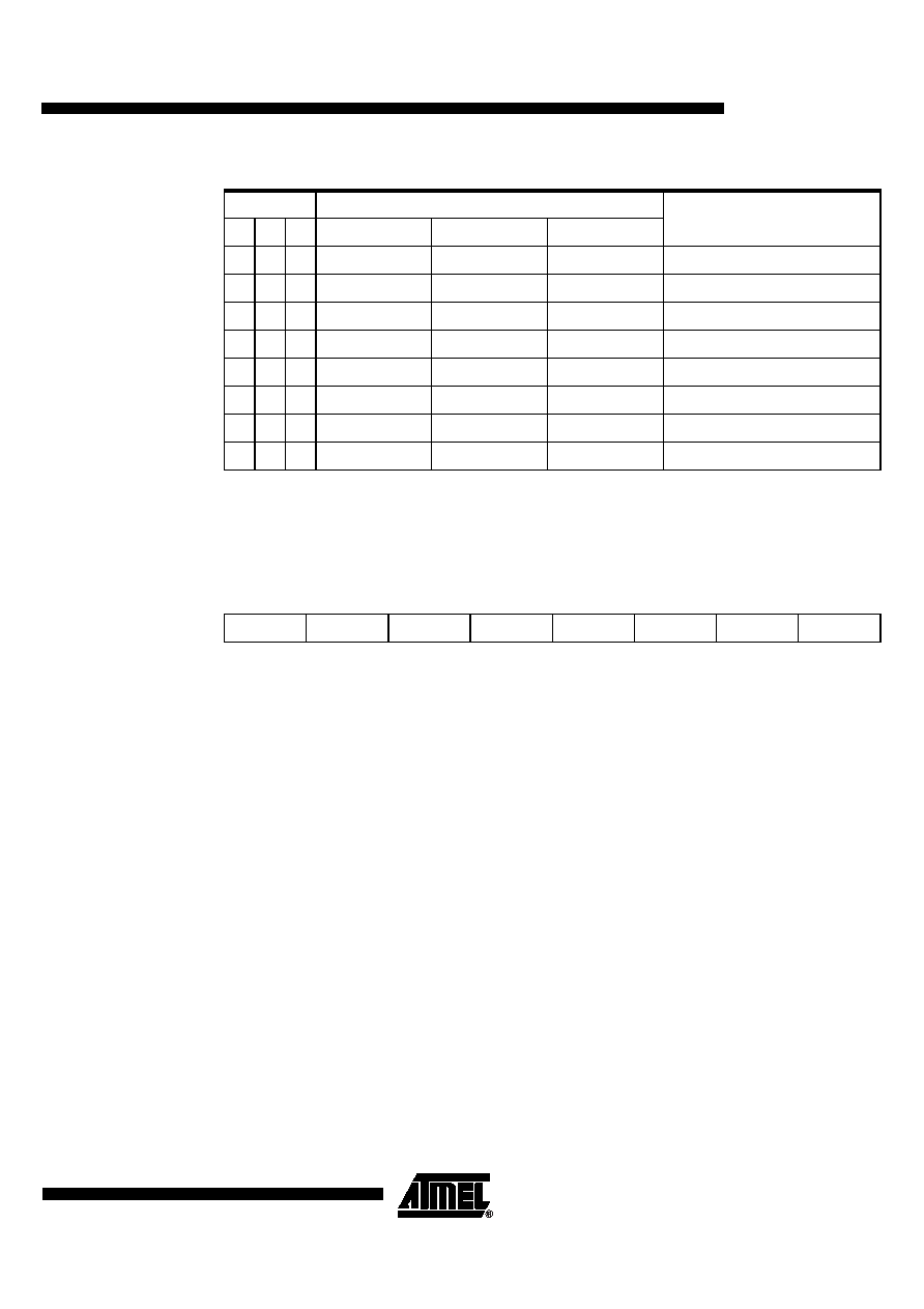 133 4173D–USB–02/06 AT89C5132 Note: 1. These bit rates are outside of the low speed standard specification limited to 100 kHz but can be used with high speed TWI components limited to 400 kHz. 20.1.2 Master Transmitter Mode In the master transmitter mode, a number of data Bytes are transmitted to a slave receiver (see Figure 20-3). Before the master transmitter mode can be entered, SSCON must be initialized as follows: SSCR2:0 define the serial bit rate (see Table 19). SSPE must be set to enable the controller. SSSTA, SSSTO and SSI must be cleared. The master transmitter mode may now be entered by setting the SSSTA bit. The TWI logic will now monitor the TWI bus and generate a START condition as soon as the bus becomes free. When a START condition is transmitted, the serial interrupt flag (SSI bit in SSCON) is set, and the status code in SSSTA is 08h. This status must be used to vector to an interrupt routine that loads SSDAT with the slave address and the data direction bit (SLA+W). The serial interrupt flag (SSI) must then be cleared before the serial transfer can continue. When the slave address and the direction bit have been transmitted and an acknowledgment bit has been received, SSI is set again and a number of status code in SSSTA are possible. There are 18h, 20h or 38h for the master mode and also 68h, 78h or B0h if the slave mode was enabled (SSAA = logic 1). The appropriate action to be taken for each of these status code is detailed in Table 20. This scheme is repeated until a STOP condition is transmitted. SSPE and SSCR2:0 are not affected by the serial transfer and are not referred to in Table 20. After a repeated START condition (state 10h) the controller may switch to the master receiver mode by loading SSDAT with SLA+R. 20.1.3 Master Receiver Mode In the master receiver mode, a number of data Bytes are received from a slave transmitter (see Figure 20-4). The transfer is initialized as in the master transmitter mode. When the START con- dition has been transmitted, the interrupt routine must load SSDAT with the 7 - bit slave address and the data direction bit (SLA+R). The serial interrupt flag (SSI) must then be cleared before the serial transfer can continue. Table 19. Serial Clock Rates SSCRx Bit Frequency (kHz) F PER Divided By 21 0 F PER = 6 MHz F PER = 8 MHz F PER = 10 MHz 0 0 0 47 62.5 78.125 128 0 0 1 53.5 71.5 89.3 112 0 1 0 62.5 83 104.2(1) 96 0 1 1 75 100 125(1) 80 1 0 0 12.5 16.5 20.83 480 1 0 1 100 133.3(1) 166.7(1) 60 1 1 0 200(1) 266.7(1) 333.3(1) 30 1 1 1 0.5 < ⋅ < 125(1) 0.67 < ⋅ < 166.7(1) 0.81 < ⋅ < 208.3(1) 96 ⋅ (256 – reload value Timer 1) SSCR2 SSPE SSSTA SSSTO SSI SSAA SSCR1 SSCR0 Bit Rate 1 0 0 0 X Bit Rate Bit Rate |
|
Link URL |
| Does ALLDATASHEET help your business so far? [ DONATE ] |
About Alldatasheet | Advertisement | Contact us | Privacy Policy | Link to Datasheet | Link Exchange | Manufacturer List All Rights Reserved©Alldatasheet.com |
| Russian : Alldatasheetru.com | Korean : Alldatasheet.co.kr | Spanish : Alldatasheet.es | French : Alldatasheet.fr | Italian : Alldatasheetit.com Portuguese : Alldatasheetpt.com | Polish : Alldatasheet.pl | Vietnamese : Alldatasheet.vn Indian : Alldatasheet.in | Mexican : Alldatasheet.com.mx | British : Alldatasheet.co.uk | New Zealand : Alldatasheet.co.nz |
|
Family Site : ic2ic.com |
icmetro.com |
 British ▼
 English
 Chinese
 German
 Japanese
 Russian
 Korean
 Spanish
 French
 Italian
 Portuguese
 Polish
 Vietnamese
 Indian
 Mexican
 British
 New Zealand