|
Electronic Components Datasheet Search |
|
|
Electronic Components Datasheet Search |
|
AT89C5132-ROTIL Datasheet(PDF) 45 Page - ATMEL Corporation |
|
|
|||||||||||||||||||||||||||||
AT89C5132-ROTIL Datasheet(HTML) 45 Page - ATMEL Corporation |
|
|
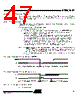
45 / 181 page 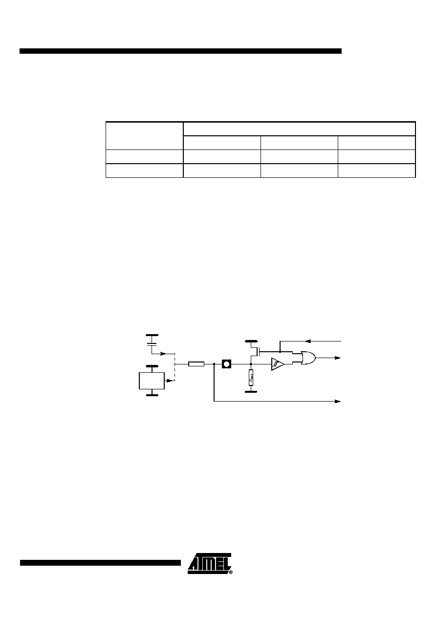 45 4173D–USB–02/06 AT89C5132 To determine the capacitor value to implement, the highest value of these 2 parameters has to be chosen. Table 17 gives some capacitor values examples for a minimum R RST of 50 KΩ and different oscillator startup and V DD rise times. Table 17. Minimum Reset Capacitor Value for a 50 k Ω Pull-down Resistor(1) Note: 1. These values assume V DD starts from 0V to the nominal value. If the time between 2 on/off sequences is too fast, the power-supply de-coupling capacitors may not be fully discharged, leading to a bad reset sequence. 11.1.2 Warm Reset To achieve a valid reset, the reset signal must be maintained for at least 2 machine cycles (24 oscillator clock periods) while the oscillator is running. The number of clock periods is mode independent (X2 or X1). 11.1.3 Watchdog Reset As detailed in Section “Watchdog Timer”, page 61, the WDT generates a 96-clock period pulse on the RST pin. In order to properly propagate this pulse to the rest of the application in case of external capacitor or power-supply supervisor circuit, a 1 k Ω resistor must be added as shown in Figure 11-2. Figure 11-2. Reset Circuitry for WDT Reset-out Usage 11.2 Reset Recommendation to Prevent Flash Corruption An example of bad initialization situation may occur in an instance where the bit ENBOOT in AUXR1 register is initialized from the hardware bit BLJB upon reset. Since this bit allows map- ping of the bootloader in the code area, a reset failure can be critical. If one wants the ENBOOT cleared in order to unmap the boot from the code area (yet due to a bad reset) the bit ENBOOT in SFRs may be set. If the value of Program Counter is accidently in the range of the boot memory addresses then a Flash access (write or erase) may corrupt the Flash on-chip memory. It is recommended to use an external reset circuitry featuring power supply monitoring to prevent system malfunction during periods of insufficient power supply voltage (power supply failure, power supply switched off). Oscillator Start-Up Time VDD Rise Time 1 ms 10 ms 100 ms 5 ms 820 nF 1.2 µF 12 µF 20 ms 2.7 µF 3.9 µF 12 µF RST VSS To CPU Core and Peripherals VDD + P VDD From WDT Reset Source VSS VDD RST 1K To Other On-board Circuitry |
|
Link URL |
| Does ALLDATASHEET help your business so far? [ DONATE ] |
About Alldatasheet | Advertisement | Contact us | Privacy Policy | Link to Datasheet | Link Exchange | Manufacturer List All Rights Reserved©Alldatasheet.com |
| Russian : Alldatasheetru.com | Korean : Alldatasheet.co.kr | Spanish : Alldatasheet.es | French : Alldatasheet.fr | Italian : Alldatasheetit.com Portuguese : Alldatasheetpt.com | Polish : Alldatasheet.pl | Vietnamese : Alldatasheet.vn Indian : Alldatasheet.in | Mexican : Alldatasheet.com.mx | British : Alldatasheet.co.uk | New Zealand : Alldatasheet.co.nz |
|
Family Site : ic2ic.com |
icmetro.com |
 British ▼
 English
 Chinese
 German
 Japanese
 Russian
 Korean
 Spanish
 French
 Italian
 Portuguese
 Polish
 Vietnamese
 Indian
 Mexican
 British
 New Zealand