|
Electronic Components Datasheet Search |
|
|
Electronic Components Datasheet Search |
|
MPM3686 Datasheet(PDF) 16 Page - Monolithic Power Systems |
|
|
|||||||||||||||||||||||||||||
MPM3686 Datasheet(HTML) 16 Page - Monolithic Power Systems |
|
|
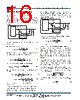
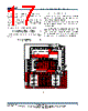
16 / 19 page  MPM3686 – 18V 20A STEP-DOWN POWER MODULE MPM3686 Rev. 1.02 www.MonolithicPower.com 16 10/13/2016 MPS Proprietary Information. Patent Protected. Unauthorized Photocopy and Duplication Prohibited. © 2016 MPS. All Rights Reserved. APPLICATION INFORMATION Setting the Output Voltage-Small ESR Capacitors When the output capacitors are all ceramic capacitors or capacitors with small ESR, external RAMP is injected through the R/C network across the inductor. The circuit connection is as follows: Figure 8 Here is the procedure to find the values for Ctrim and Rtrim: a) Determine the Ton FREQ ON IN 5.3 R (K ) T(ns) V(V) 0.4 (10) b) Determine Ctrim. Choose a VRAMP around 10mV-30mV for most of the applications. ) ns ( T ) V ( V ) K ( R ) V ( V ) V ( V ) pF ( C ON RAMP OUT IN TRIM 3 (11) c) Find the average feedback voltage VFB RAMP FB _ AVG REF V(V) V(V) V (V) 2 (12) d) Calculate Rtrim to get the desired output voltage: ) K ( ) ) V ( V ) V ( V ( ) K ( R AVG _ FB OUT o 10 1 (13) O TRIM O R (K ) 300(K ) R(K ) 300(K ) R (K ) (14) Setting the Output Voltage-Large ESR Capacitors If one or more piece of the output capacitors have large ESR, then there is no need of external RAMP. Otherwise, it’ll generate group pulses at light load conditions. The Ctrim is still recommended to boost the phase margin of the system. A value between 100pF and 2.2nF is recommended. The circuit connection can be made as the following: Figure 9 The Rtrim can be determined as follows to obtain the desired output voltage: OUT REF TRIM REF VV R(K ) 10 V (15) Input Capacitor The input current to the step-down power module is discontinuous, and therefore, it requires a capacitor to supply the AC current to the step- down power module while maintaining the DC input voltage. Use ceramic capacitors for best performance. During layout, Place the input capacitors as close to the IN and GND pins as possible. The capacitance can vary significantly with temperature. Use capacitors with X5R or X7R ceramic dielectrics because they are fairly stable over a wide temperature range. The capacitors must also have a ripple current rating that exceeds the converter’s maximum input ripple current. Estimate the input ripple current as follows: ) V V 1 ( V V I I IN OUT IN OUT OUT CIN (16) The worst-case condition occurs at VIN = 2VOUT, where: 2 I I OUT CIN (17) |
|
|
Link URL |
| Does ALLDATASHEET help your business so far? [ DONATE ] |
About Alldatasheet | Advertisement | Contact us | Privacy Policy | Link to Datasheet | Link Exchange | Manufacturer List All Rights Reserved©Alldatasheet.com |
| Russian : Alldatasheetru.com | Korean : Alldatasheet.co.kr | Spanish : Alldatasheet.es | French : Alldatasheet.fr | Italian : Alldatasheetit.com Portuguese : Alldatasheetpt.com | Polish : Alldatasheet.pl | Vietnamese : Alldatasheet.vn Indian : Alldatasheet.in | Mexican : Alldatasheet.com.mx | British : Alldatasheet.co.uk | New Zealand : Alldatasheet.co.nz |
|
Family Site : ic2ic.com |
icmetro.com |
 British ▼
 English
 Chinese
 German
 Japanese
 Russian
 Korean
 Spanish
 French
 Italian
 Portuguese
 Polish
 Vietnamese
 Indian
 Mexican
 British
 New Zealand